Download as PDF
How To Save as PDF
- Press Ctrl+P
- Click the dropdown arrow beneath Printer
- Click Microsoft Print to PDF
- Click Print and Save to a directory of your choice

DOC.#82061
DOC.#82061
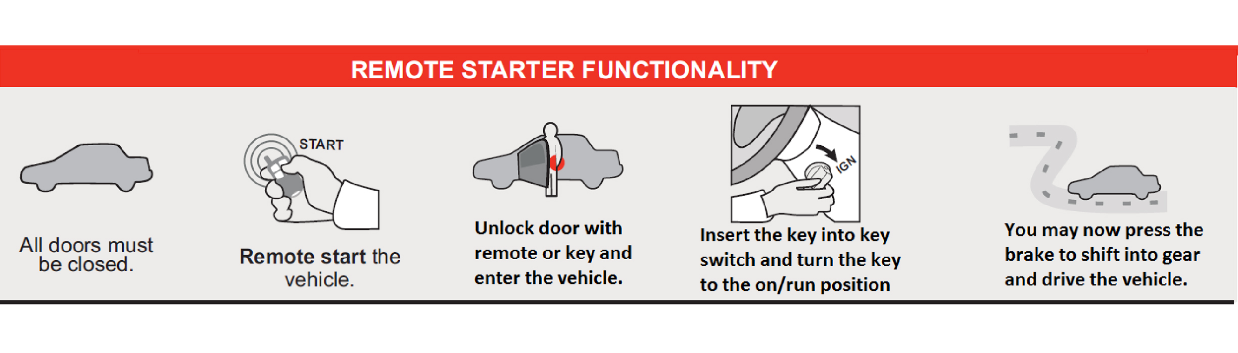
TIP SHEETB-1491-4532006 Toyota TACOMAKey-To-Start
Thank you for purchasing your remote start from MyPushcart.com - an industry leader in providing remote starts to do-it-yourself installers since 1999. The purpose of this tip sheet is to help you organize your installation. If you are having difficulties please contact our Technical Support Department by clicking here https://mypushcart.com/helpme/ OR PHONE: (520) 572-2220 M-F 9-5 ARIZONA time.
Help us help you:
 The best way to get support the soonest is to open an online ticket. Phone calls are always welcome. The phones are answered by receptionists who can take your information and create the same ticket you can create using the link above. Tickets are handled in the order in which they are received. THANK YOU
Disclaimer
Neither the manufacturer nor the distributor of these components are responsible for damages of any kind either indirectly or directly caused by the components, except for the replacement of the components in case of manufacturing defects. This guide is subject to change without notice. Refresh your browser cache or use different browser (Edge, Chrome, Firefox, etc.) to view the latest update.
A few very important things before you get started:
Read the entire tip sheet. There are several safety tips there that you need to know before you start.
Avoid using a test light to probe wires. Test lights can set off airbags if you probe the wrong wire. Your vehicle wiring chart will identify the correct wires that you’ll be tapping on to in your car. If you must probe, use a digital multi-meter. They’re inexpensive and won’t set off airbags.
Only compatible with automatic transmission vehicles manufactured for sale in the US and Canada.
⇒ Firmware pre-loaded: As part of the service MPC provides, we have already flashed the compatible 4.06 firmware version into your Key-Override-All bypass module for you so you are ready to begin the installation in the vehicle. You will need to program the module to the vehicle when the installation is complete.
REMOTE START ACTIVATION
Overview
There are 5 basic steps to this remote start installation:
1. Preparation
2. Wiring
3. Programming
4. Testing the system
5. Finishing up!
STEP 1: Preparation
Beginning the Installation:
Tip #1 – Where Everything Goes
• When you open up your remote start, you’re going to see a whole bunch of wires. Don’t be intimidated – you’re only going to be using a few of them. The remote starters are designed with wiring options for a variety of cars and no car is going to use all of them. The wire charts and system wiring diagram will show you the wires that you’re going to need and where they connect in your vehicle. Any wires that are not shown to connect in this guide will not need to be connected.
• Remote start and bypass modules – Before you start wiring, look for a location where there’s some open space that will fit the modules. Pay attention to moving parts like the pedals, e-brake and steering column. Be sure to route your wiring away from those areas. Carefully remove the lower knee bolster, plastic steering column shroud, and any other panels required to gain access to the needed vehicle plugs. Remember the order that you remove the panels. It is best to route your wires along with the vehicles factory wires, as this is typically a safe location and it keeps the install neat. Once you have accessed the needed locations in the vehicle use the plugs, pin positions in the plugs, and wire colors shown in this guide to identify the correct wires that you will need to connect from the remote starter to the vehicle. In most cases, the wires on the remote start are way longer than needed. Trim off the excess wire when you make your connections, but leave some slack, this will allow you some flexibility when it comes time to stow the remote start after the installation is completed.
How to Make Wire Connections
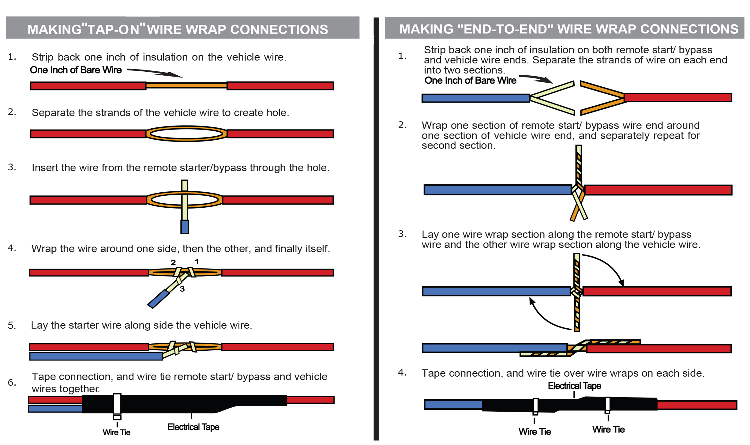
Strip - Poke - Wrap and Tape method is the best wire connection that you can make. You MUST use this method for the RX and TX wire connections. Do not solder unless you know how to do it really well.
Click here for directions on how to Strip/Wrap/Tape the wires
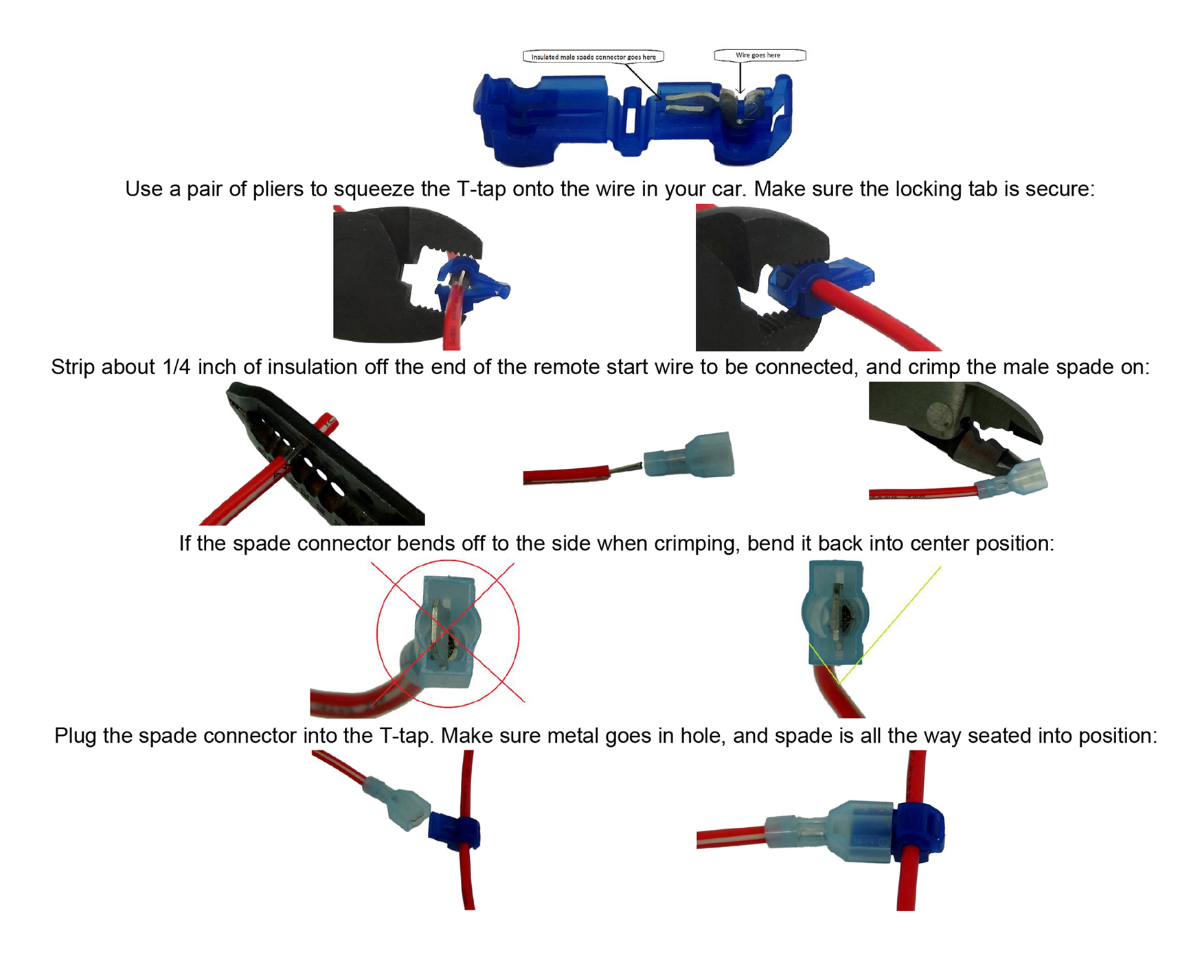
The Strip - Poke - Wrap and Tape method shown above is the most reliable for remote start installations. Your kit may include T-Tap connectors that can be used on any connections except for the RX and TX wire connections.
Click here for directions on how to use a T-Tap
WHERE TO FIND YOUR WIRES
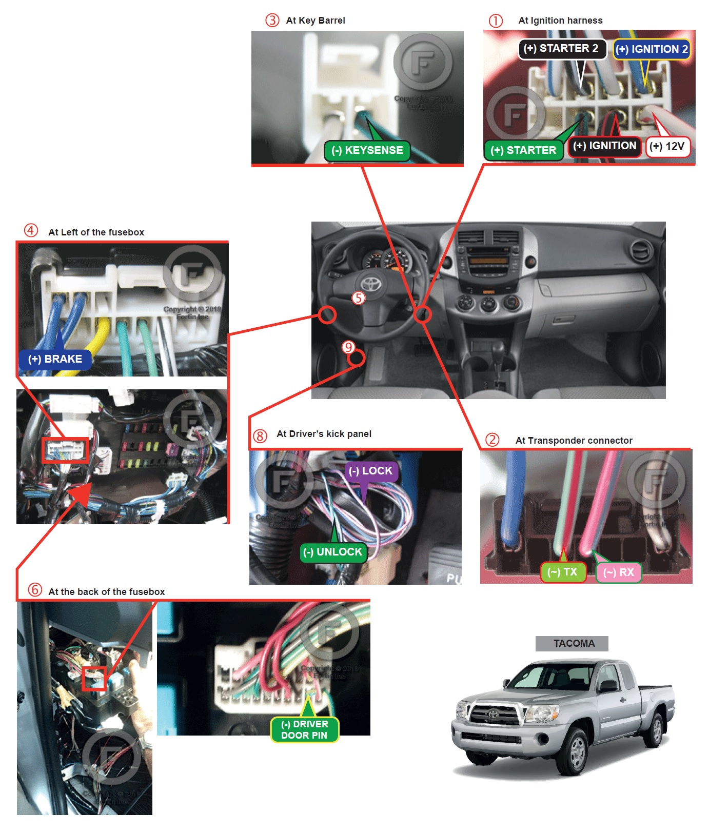
Wiring Diagram
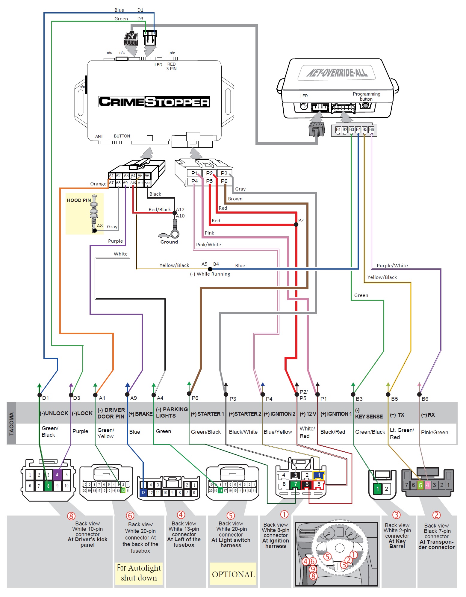
Remote Start Connections
Ground – Connect the Black wire from the 12-pin plug to ground (bare metal in your vehicle).
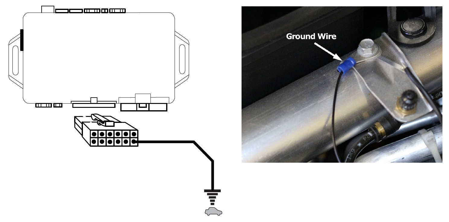
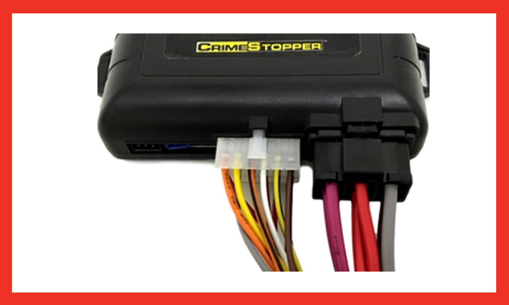
Insert the 6 and 12-pin plugs into the remote start module.
Optional Connections
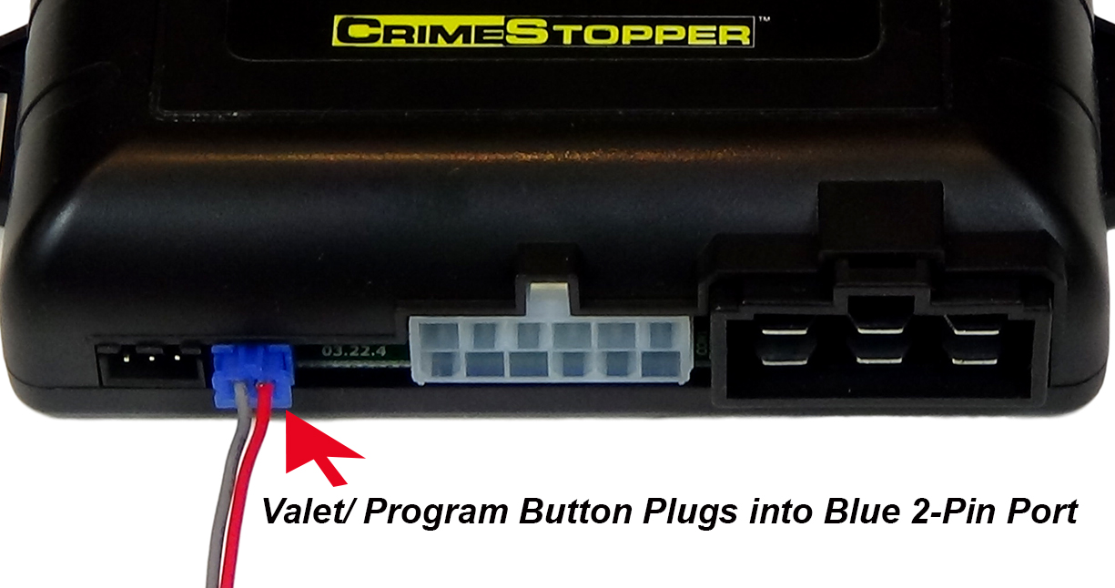
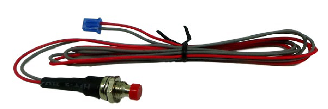
1. Valet Switch – The Crimestopper remote starter comes with a valet programming button with a small blue 2-pin plug. This is used for programming, and while it is not essential for the remote start operation, we recommend installing this so that just in case it is needed in the future, it does not get lost. Requires a ¼” hole. Usually put in the driver’s kick panel (that’s the area forward of the door), the driver’s side of the center console, or the underside of the dash.
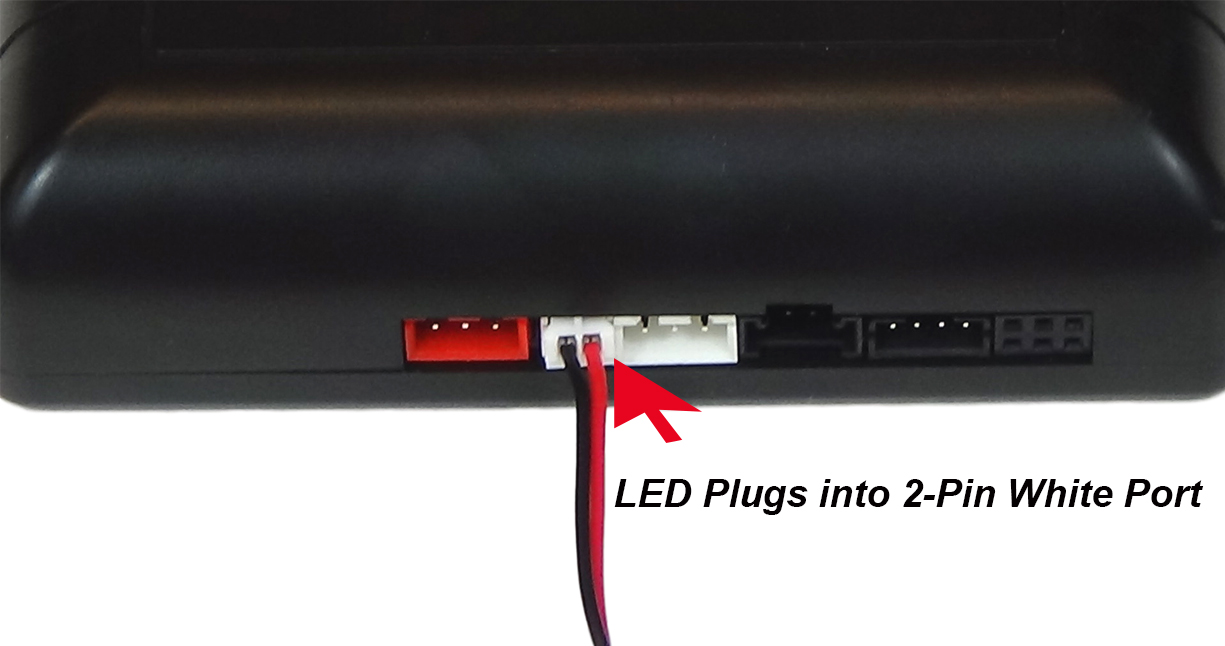
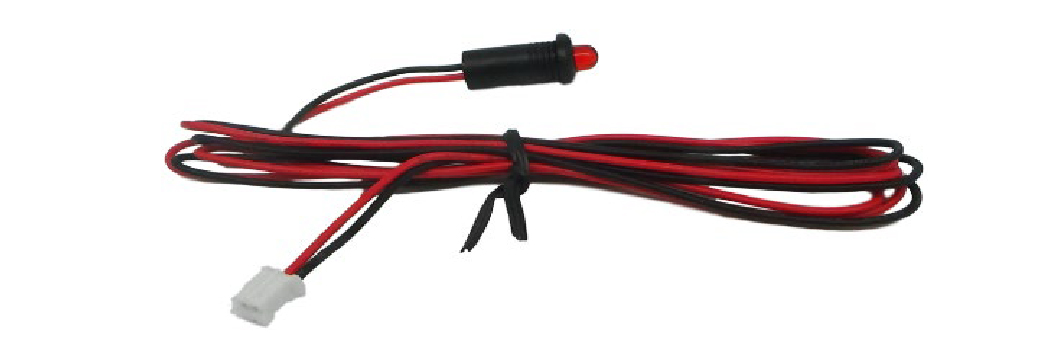
2. LED – The Crimestopper remote starter comes with an LED with a small white 2-pin plug. This is a status indicator and can be useful for diagnostics but is not essential for remote start operation. Requires a ¼” hole. Usually put in the driver’s kick panel (that’s the area forward of the door), the driver’s side of the center console, or the underside of the dash.
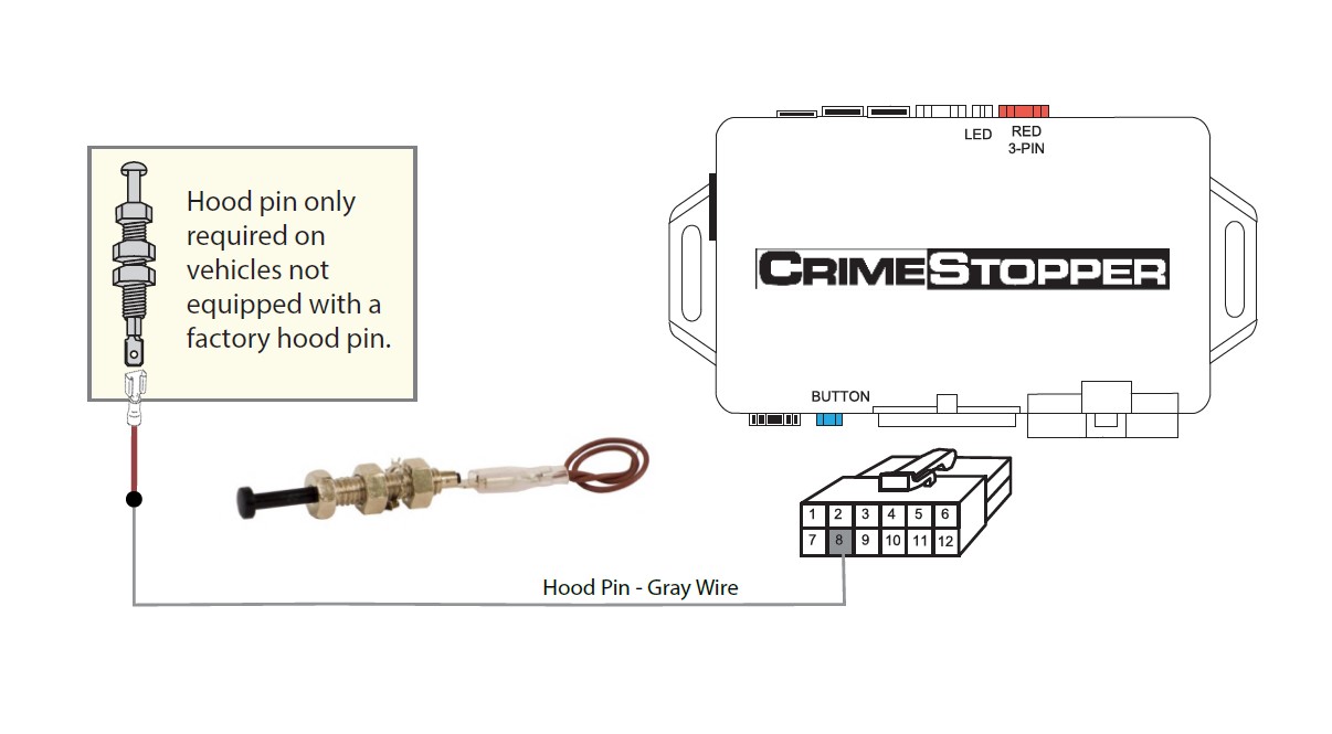
3. Hood Pin -This is an OPTIONAL connection and is not needed for the remote start to operate.
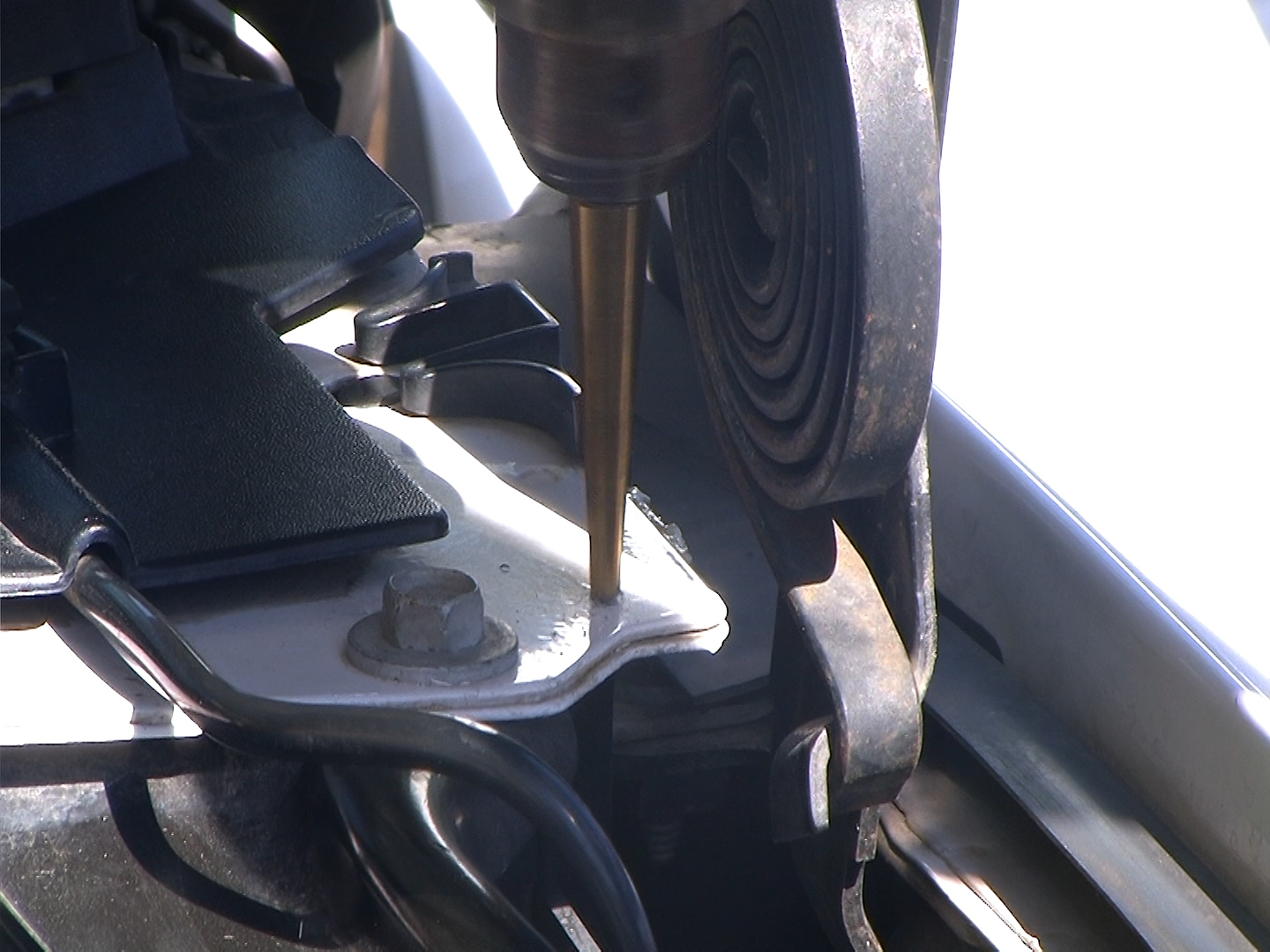
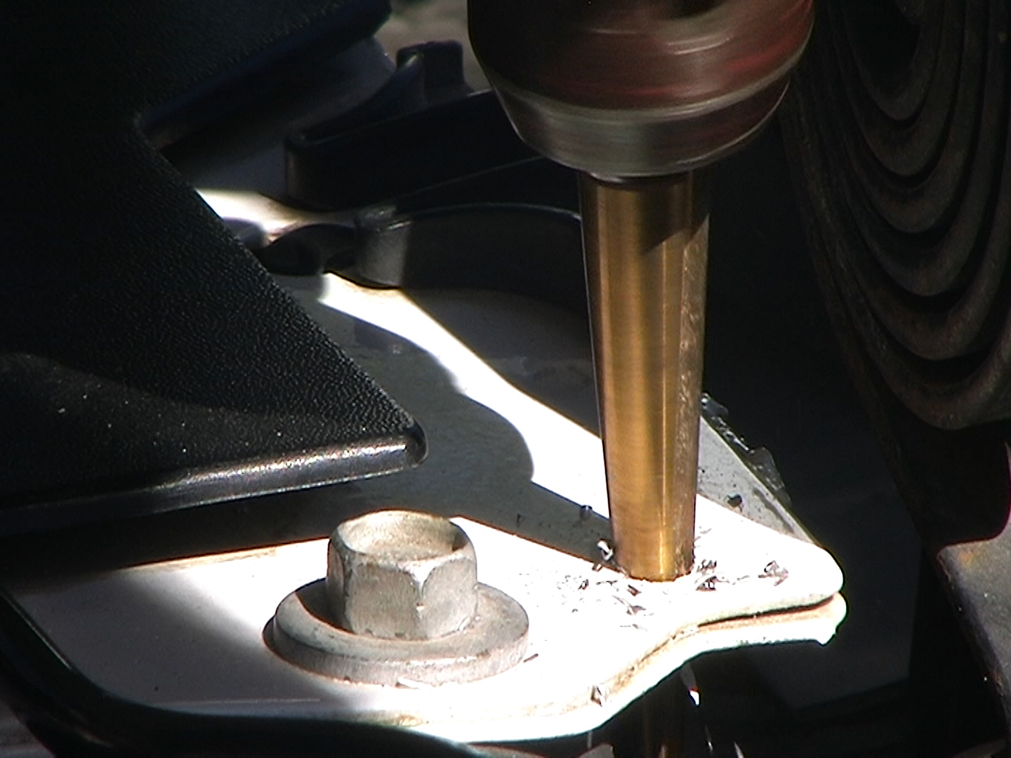
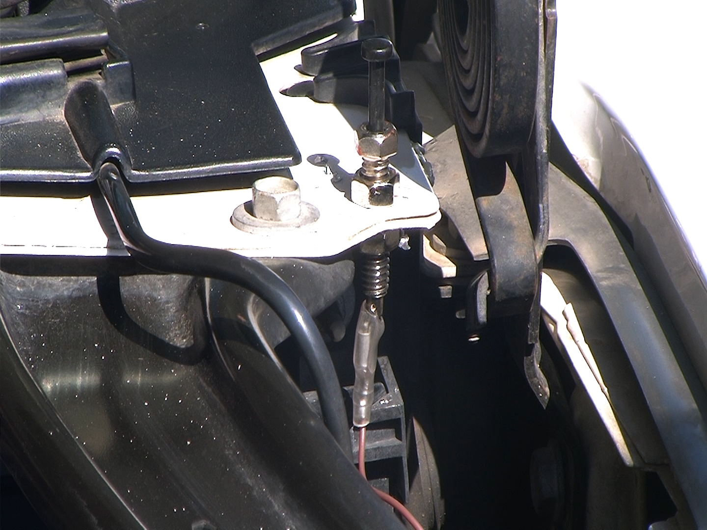
If your vehicle is not equipped with a hood pin switch you can install an aftermarket one as a protection feature. The hood pin will prevent you from accidentally activating the remote start if the hood is open. You will need to drill a 3/8” hole in metal under the hood and mount the aftermarket hood pin switch. Make sure that you position the switch so that when you close the hood it pushes the plunger down on the hood pin switch. Route a wire from the pin switch carefully through the firewall either by way of a plastic grommet or use a factory rubber grommet to pass the wire through. Then connect the hood pin switch wire to the Gray wire in the 12-pin connector as shown.
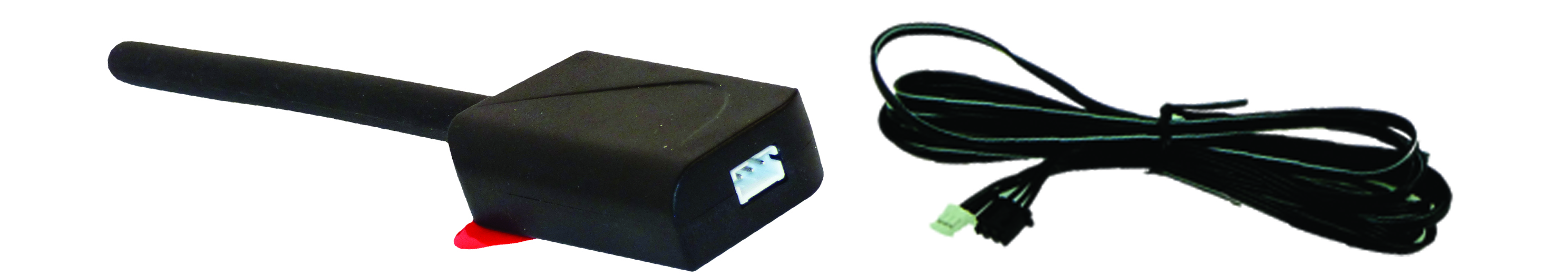
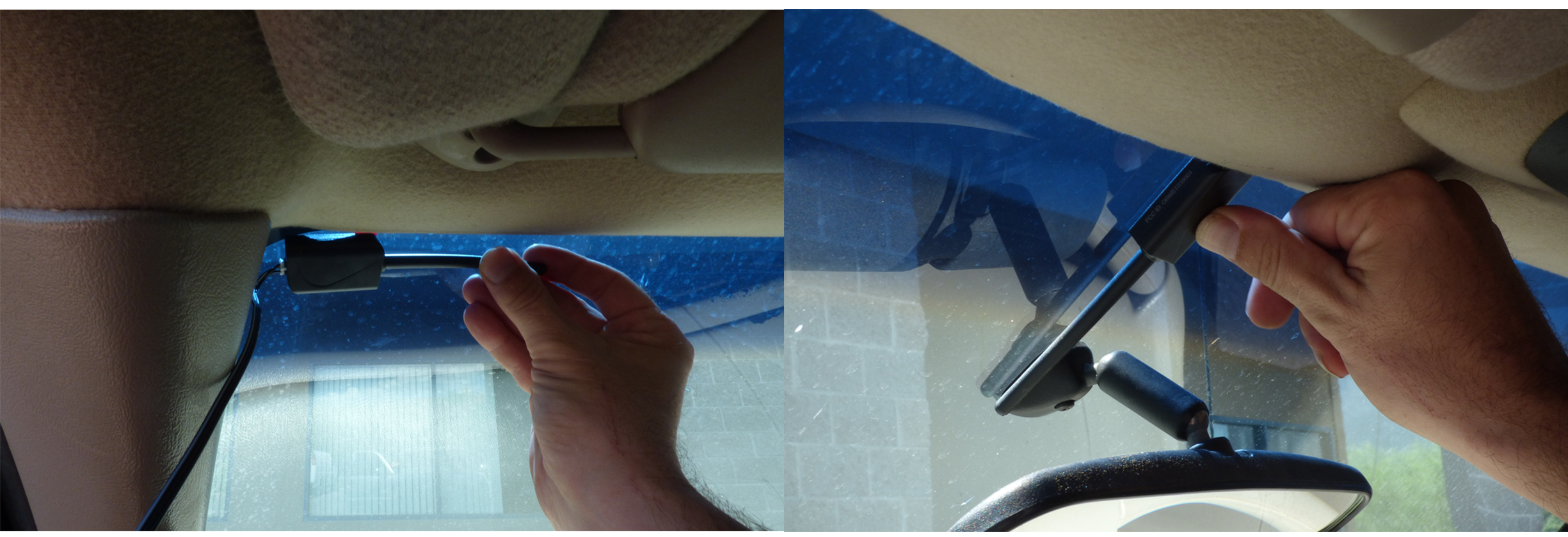
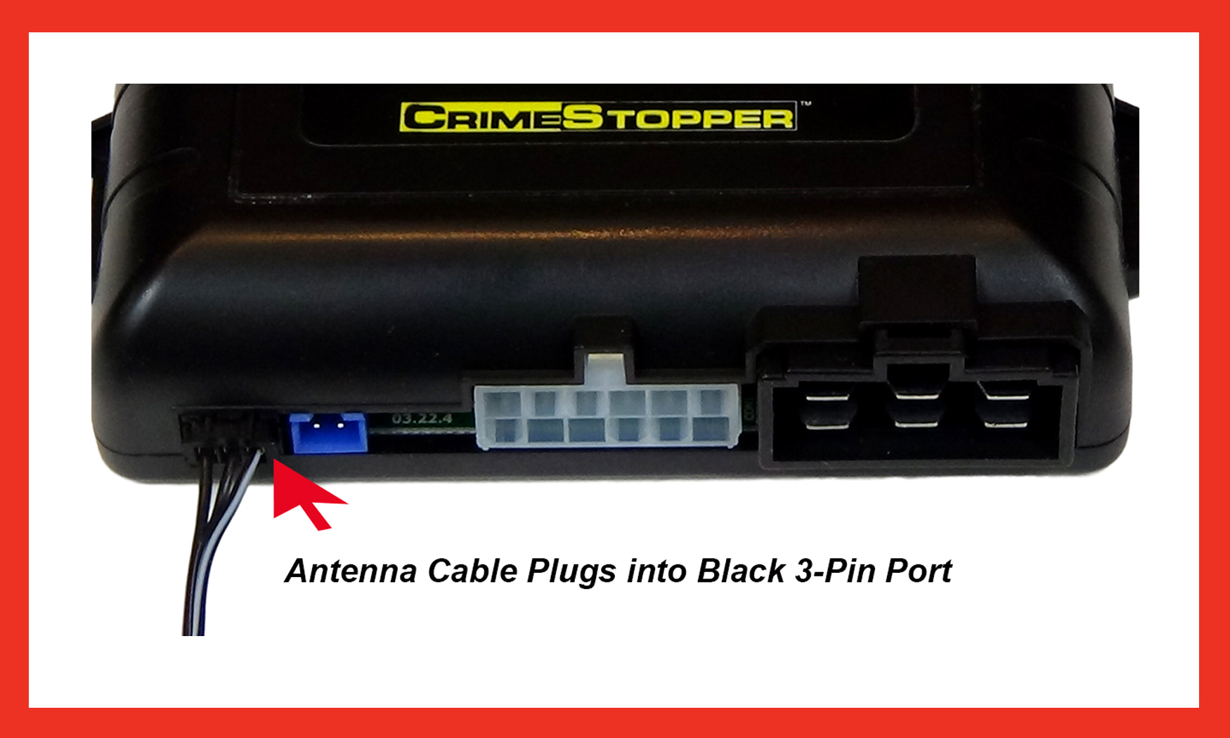
Mounting and Connection of Antenna
The kit comes with a long-range antenna and antenna wire.

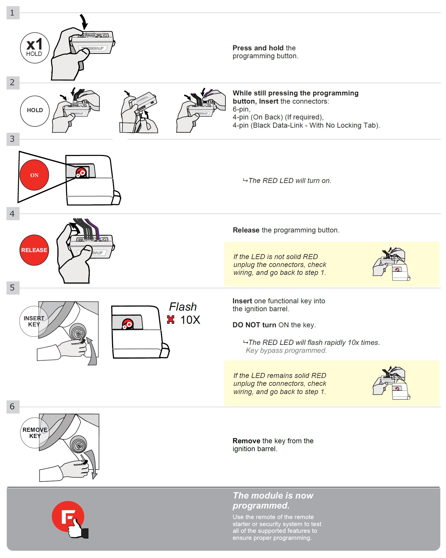
STEP 3: Programming
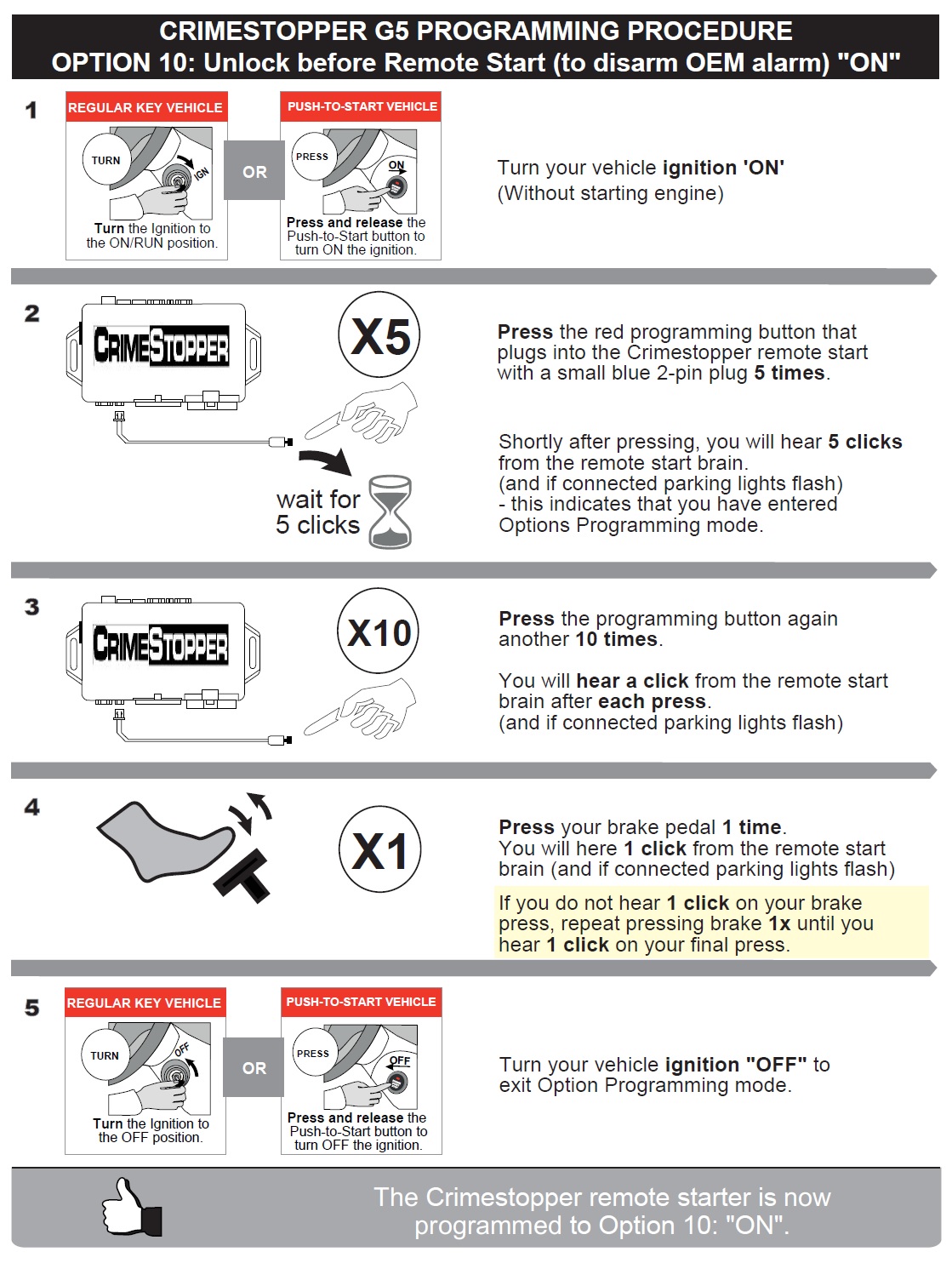
OPTION 10 - UNLOCK BEFORE REMOTE START (to disarm OEM alarm)
This option is used to disarm an OEM alarm system before remote start. To change this option follow the directions below.
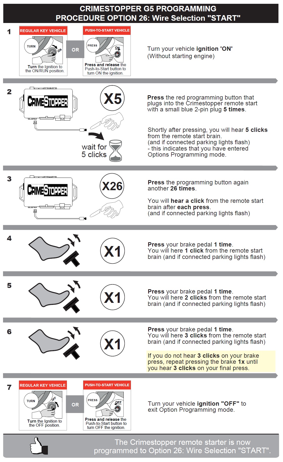
Option #26: “START” – This will make the high current GRAY wire act as a starter output, instead of its default “accessory” function.
To change this option follow the directions below.
STEP 4: Testing the system
Once all wiring and programming are done, you should test the system to make sure everything is working properly before you finish up the installation.
There is no need to program the new remotes that came with this remote start kit. We have already paired the remotes to your remote starter for you so they are ready for use.
MPC remote start kits put the controls at your fingertips. This system can accept up to 4 long range remotes of the same "1-Way / 2-Way" type at a time. Your remote starter also has a dedicated port to accept a smartphone module which you can add to the system and all controllers will function together.
Click the link below if you wish to order additional / replacement remotes or a different controller type including our smartphone interface module, and access complete instructions on how to connect and program each to this specific system:
⇒ Using the 5-Button 1-Way remote control:
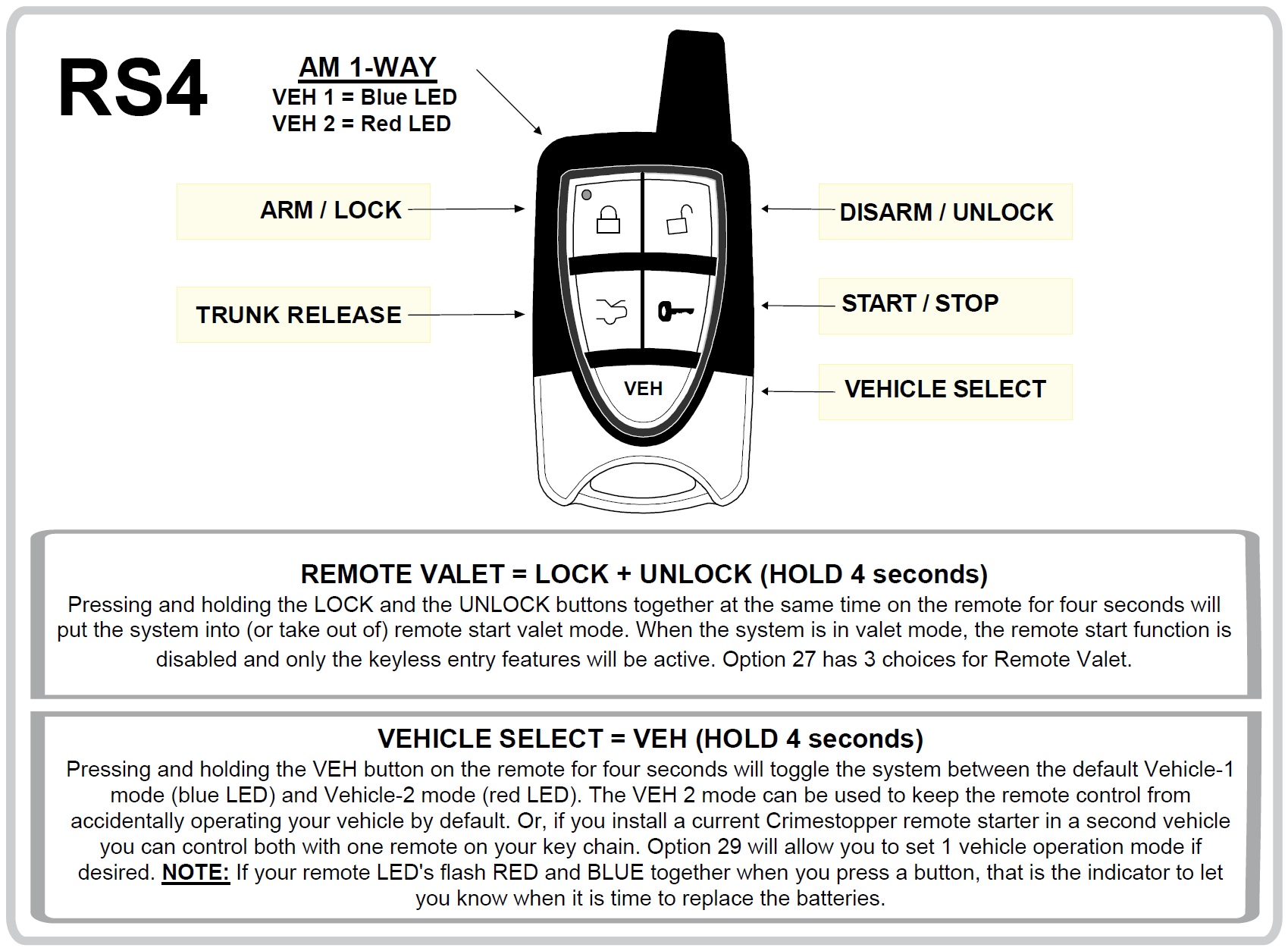
⇒ Test the keyless entry:
» One quick half second press on the remote LOCK button should lock the vehicle doors.
» One quick half second press on the remote UNLOCK button should unlock the vehicle doors.
» One three second press on the remote TRUNK button will activate the optional trunk release output.
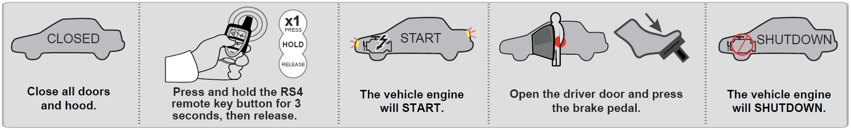
⇒ Test the remote starter:
1. Take all vehicle keys with you, and exit the vehicle. Make sure all doors and hood are closed.
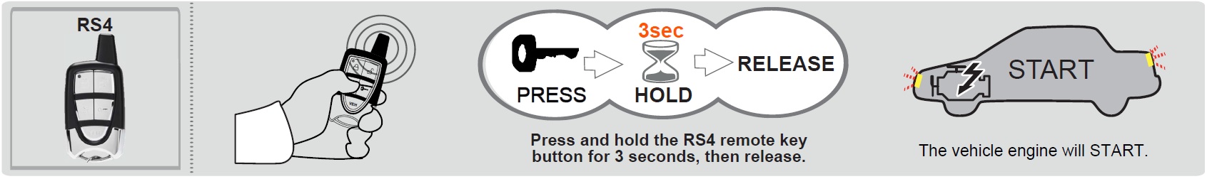
2. Press the key button on the RS4 remote for approximately three seconds and release to activate the remote start.
3. A few seconds later the vehicle gauges should power up. Then a few more seconds later the starter should crank and the engine turn on. Make sure the vehicle stays running at least a couple minutes, and that the climate controls are working. If the optional parking light wire is connected, the parking lights will turn on when the vehicle is remote started as a visual indicator. The engine will remain running for 20 minutes (default) or until it receives signal from a shutdown mechanism.
4. Enter the vehicle and step on the brake pedal.
5. Pressing the brake pedal is the shutdown mechanism in most applications. Opening a door is the shutdown mechanism for some push-to-start vehicle applications (refer to KEY TAKEOVER section). Make sure the shutdown mechanism is working. The remote starter can also be shutdown by another three second press and release of the key button command from the RS4 remote, or opening the hood.
When the system receives an activation command and you hear clicks from the Crimestopper remote start module brain but the vehicle fails to start, the status LED that plugs into the Crimestopper brain will flash a certain number of times separated by a pause in a pattern until ignition is cycled to reset the code. The number of times the status LED flashes in-between each pause corresponds to a remote start diagnostic error code. This will tell you why the remote starter last shutdown. The codes are as follows:
1 Parking Light Flash (1 LED Flash) = Problem with Brake Switch.
2 Parking Light Flashes (2 LED Flashes) = Problem with Hood Switch.
3 Parking Light Flashes (Solid LED) = Valet Service Mode.
5 Parking Light Flashes (5 LED Flashes) = Ignition On before Remote Start or Tach problem.
6 Parking Light Flashes (6 LED Flashes) = Tach Problem (Tach signal without engine running)
7 Parking Light Flashes (7 LED Flashes) = Manual Transmission Error.
* If your testing was unsuccessful, go back and re-check your wiring and programming. Make sure there are no bent pins or loose wires, and that all vehicle plugs you may have disconnected in the area you were working are properly re-connected. If you used T- Taps, make sure they are all attached correctly. Remember that T-Taps should never be used on data connections. Depending on the vehicle, those connections could be labeled Data, Can Hi, Can Low, IMMO, IMI, RX, TX or Passlock.
STEP 5: Finishing up!
After confirming that everything works properly, cap off or tape the ends of any wires you’re not using to avoid grounding or other contacts.
• Now gather up all the wiring and neatly bundle it together using zip ties or electrical tape to prevent the wires from interfering with any of the moving parts under the dash.
• Test the system often when you are putting your vehicle back together.
• Find a secure place to put the remote start module and use zip ties to secure it. Be careful not to zip tie near your connections as it may create a bad connection.
• Replace any interior vehicle panels that were removed to gain access to the needed wires, in reverse order that they were removed.
• Test the system as you reinstall the panels in your vehicle to make sure you do not pull something loose or pinch a wire. Be careful not to run a screw through a wire or pinch a wire while reinstalling panels.
KEY TAKEOVER
Copyright 2025 Digitel LLC