Download as PDF
How To Save as PDF
- Press Ctrl+P
- Click the dropdown arrow beneath Printer
- Click Microsoft Print to PDF
- Click Print and Save to a directory of your choice

DOC.#
DOC.#
TIP SHEETB-4741-5932004 Chevrolet AVALANCHEKey-To-Start
Thank you for purchasing your remote start from MyPushcart.com - an industry leader in providing remote starts to do-it-yourself installers since 1999. The purpose of this tip sheet is to help you organize your installation. If you are having difficulties please contact our Technical Support Department by clicking here https://mypushcart.com/helpme/ OR PHONE: (520) 572-2220 M-F 9-5 ARIZONA time.
Help us help you:
 The best way to get support the soonest is to open an online ticket. Phone calls are always welcome. The phones are answered by receptionists who can take your information and create the same ticket you can create using the link above. Tickets are handled in the order in which they are received. THANK YOU
Disclaimer
Neither the manufacturer nor the distributor of these components are responsible for damages of any kind either indirectly or directly caused by the components, except for the replacement of the components in case of manufacturing defects. This guide is subject to change without notice. Refresh your browser cache or use different browser (Edge, Chrome, Firefox, etc.) to view the latest update.
Only compatible with automatic transmission vehicles manufactured for sale in the US and Canada.
A few very important things before you get started:
Read the entire tip sheet. There are several safety tips there that you need to know before you start.
Avoid using a test light to probe wires. Test lights can set off airbags if you probe the wrong wire. Your vehicle wiring chart will identify the correct wires that you’ll be tapping on to in your car. If you must probe, use a digital multi-meter. They’re inexpensive and won’t set off airbags.
REMOTE START ACTIVATION
⇒ Firmware pre-loaded: As part of the service MPC provides, we have already flashed the compatible 3.06 firmware version into your INT-SL data / bypass module for you so you are ready to begin the installation in the vehicle. You will need to program the module to the vehicle when the installation is complete.
Overview
There are 5 basic steps to this remote start installation:
1. Preparation
2. Wiring
3. Programming
4. Testing the system
5. Finishing up!
STEP 1: Preparation
Beginning the Installation:
Tip #1 – Where Everything Goes
• When you open up your remote start, you’re going to see a whole bunch of wires. Don’t be intimidated – you’re only going to be using a few of them. The remote starters are designed with wiring options for a variety of cars and no car is going to use all of them. The wire charts and system wiring diagram will show you the wires that you’re going to need and where they connect in your vehicle. Any wires that are not shown to connect in this guide will not need to be connected.
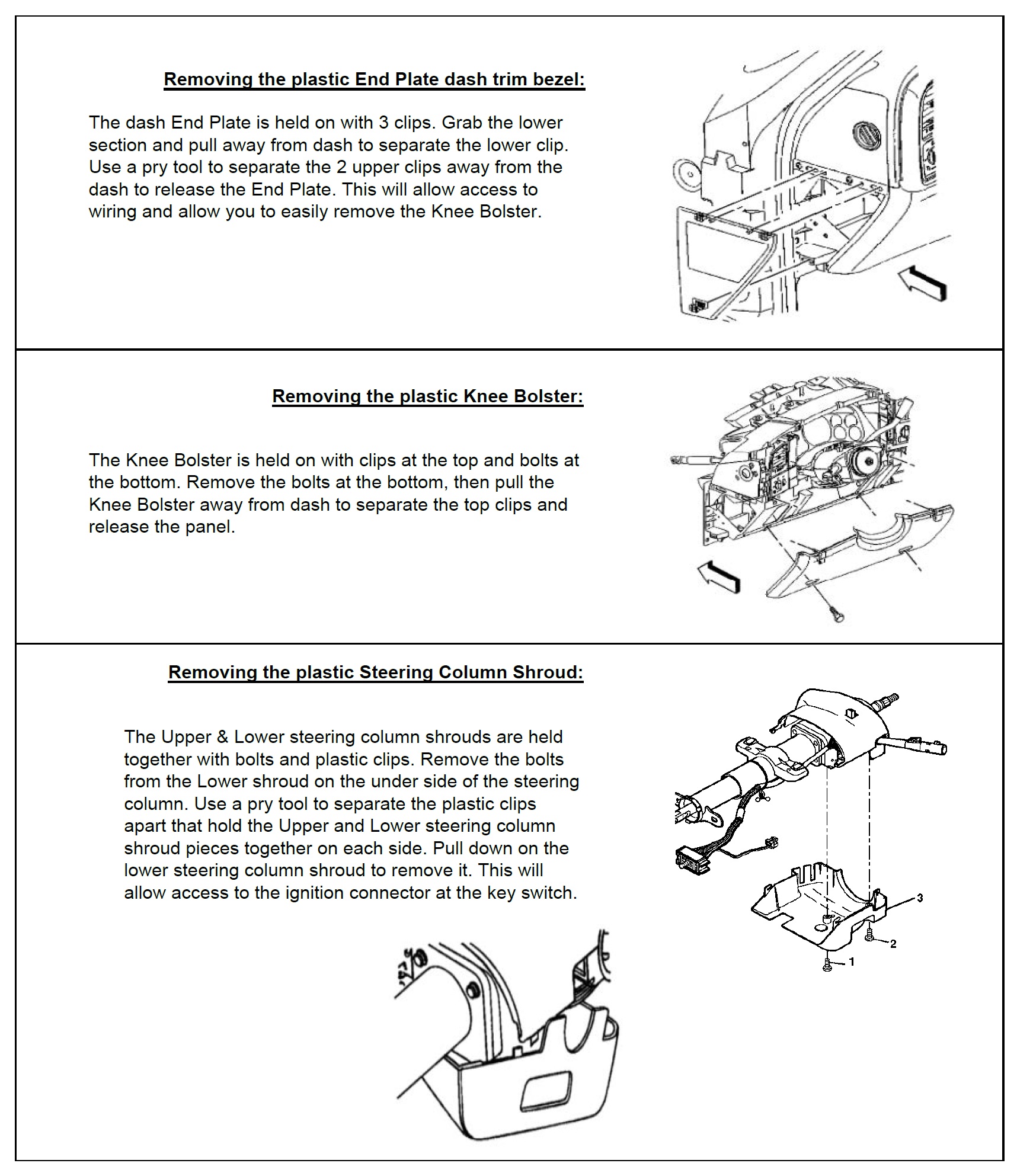
• Remote start and bypass modules – Before you start wiring, look for a location where there’s some open space that will fit the modules. Pay attention to moving parts like the pedals, e-brake and steering column. Be sure to route your wiring away from those areas. Carefully remove the lower knee bolster, plastic steering column shroud, and any other panels required to gain access to the needed vehicle plugs. Remember the order that you remove the panels. It is best to route your wires along with the vehicles factory wires, as this is typically a safe location and it keeps the install neat. Once you have accessed the needed locations in the vehicle use the plugs, pin positions in the plugs, and wire colors shown in this guide to identify the correct wires that you will need to connect from the remote starter to the vehicle. In most cases, the wires on the remote start are way longer than needed. Trim off the excess wire when you make your connections, but leave some slack, this will allow you some flexibility when it comes time to stow the remote start after the installation is completed.
STEP 2: Wiring
How to Make Wire Connections
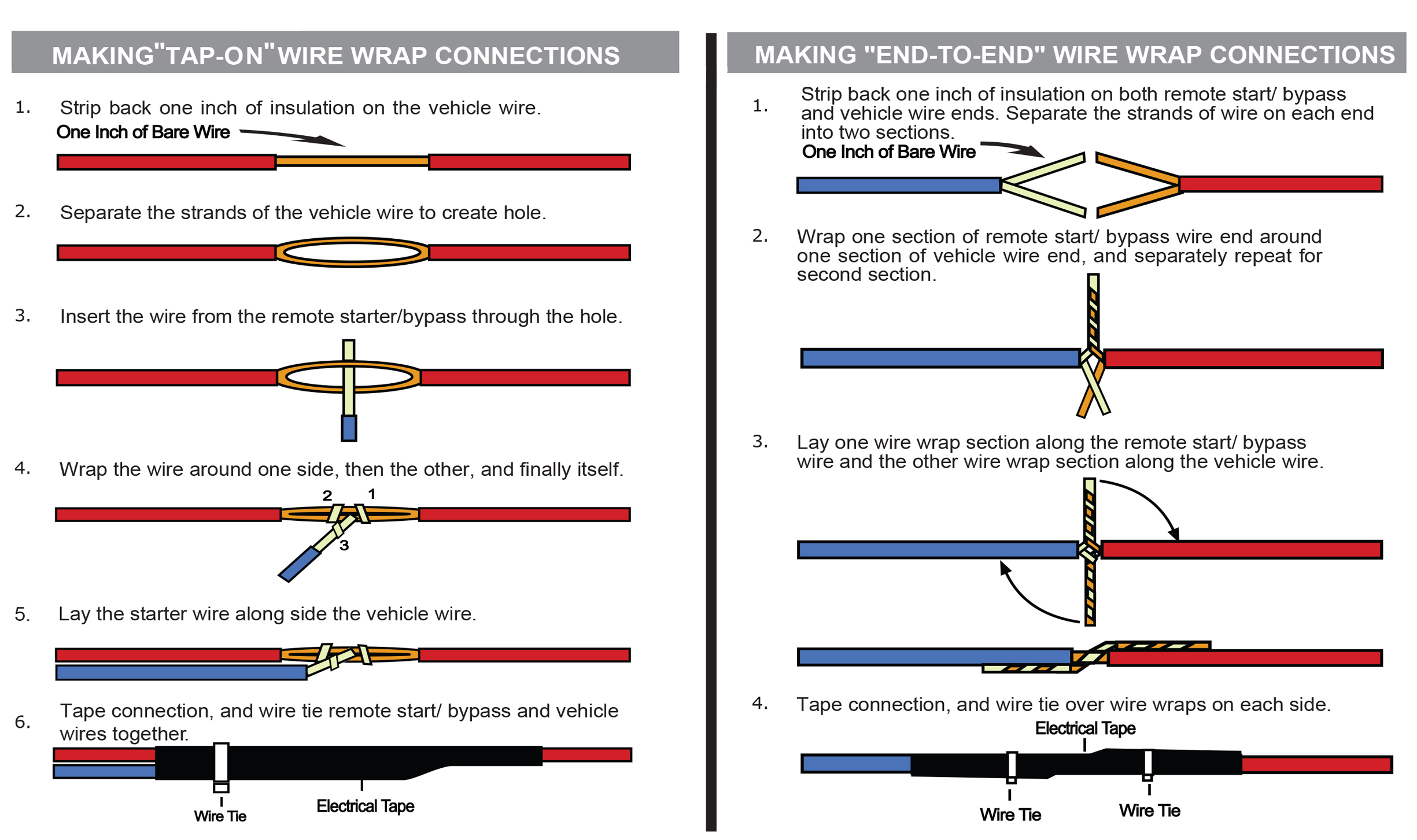
Strip - Poke - Wrap and Tape method is the best wire connection that you can make. You MUST use this method for any data wire connection(s). T-Taps should never be used on data connections. If required for your installation, data connections may be labeled: CAN HIGH, CAN LOW, IMMO, IMI, IMO, RX, TX, or Passlock. Do not solder unless you know how to do it really well.
Click here for directions on how to Strip/Poke/Wrap/Tape the wires
The recommended Strip - Poke - Wrap and Tape method shown above is the most reliable for remote start installations. Your kit may include T-Tap connectors that can make your connections easier, and still perform reliably when used correctly. T-taps can be used on any connections except for the Data wire connection(s).
Click here for directions on how to use a T-Tap
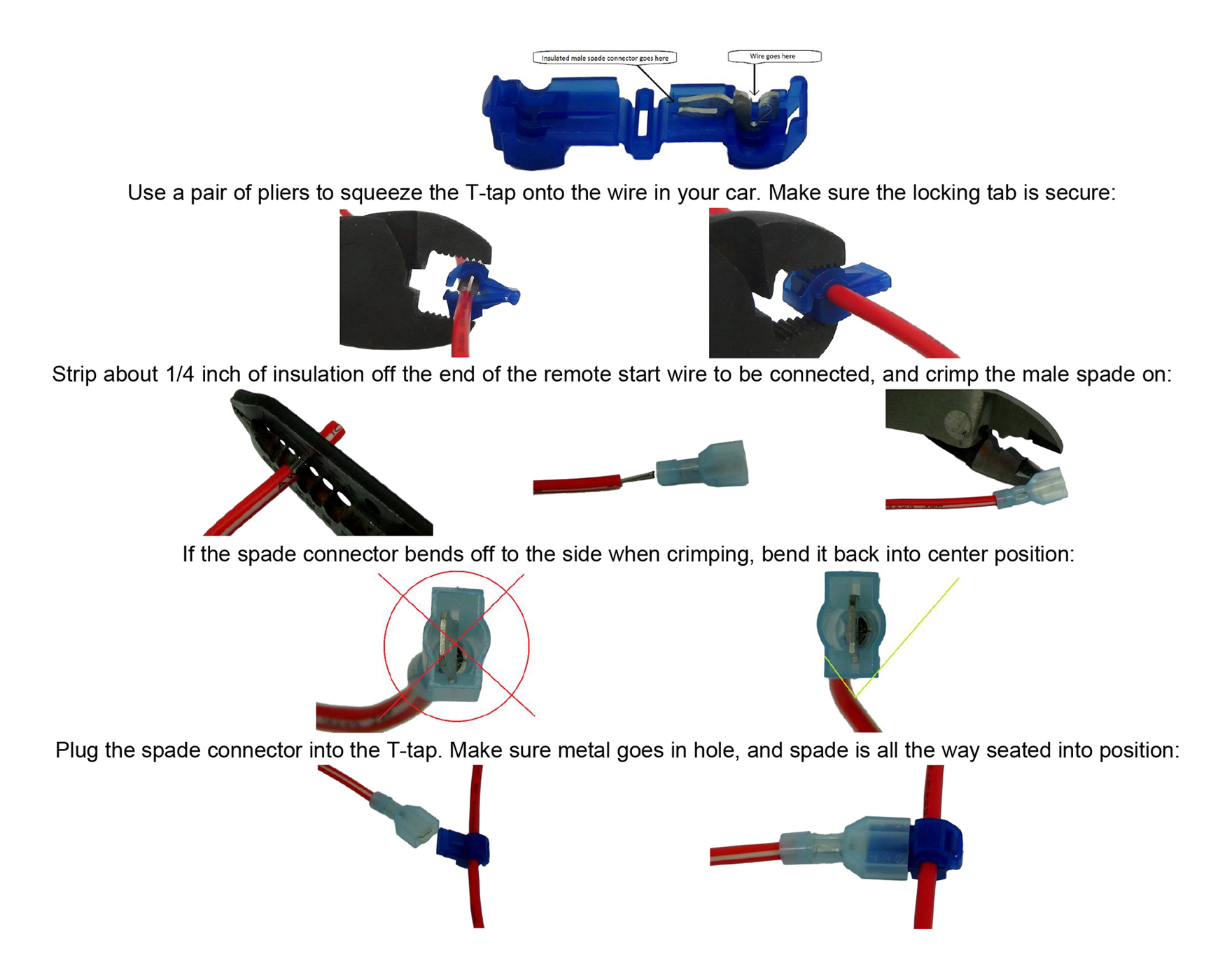
Optional Connections
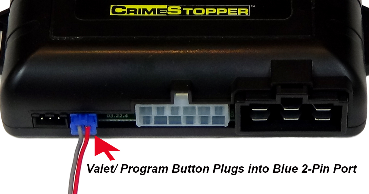
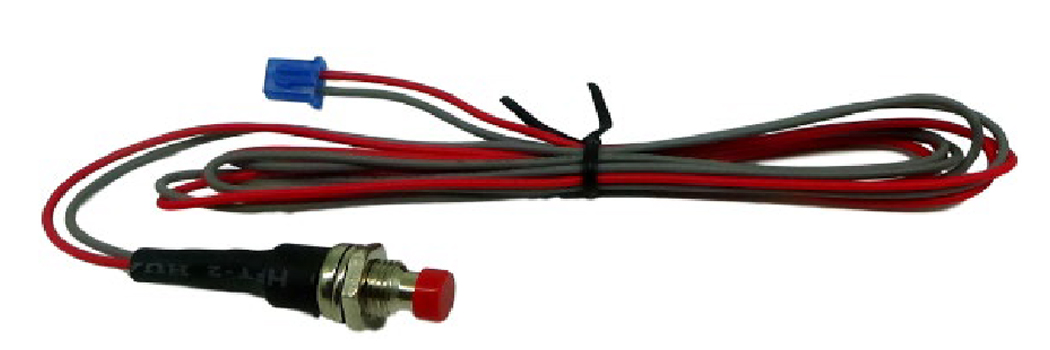
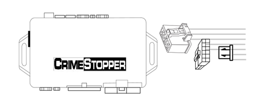
1. Valet Switch – The Crimestopper remote starter comes with a valet programming button with a small blue 2-pin plug. This is used for programming, and while it is not essential for the remote start operation, we recommend installing this so that just in case it is needed in the future, it does not get lost. Requires a ¼” hole. Usually put in the driver’s kick panel (that’s the area forward of the door), the driver’s side of the center console, or the underside of the dash.
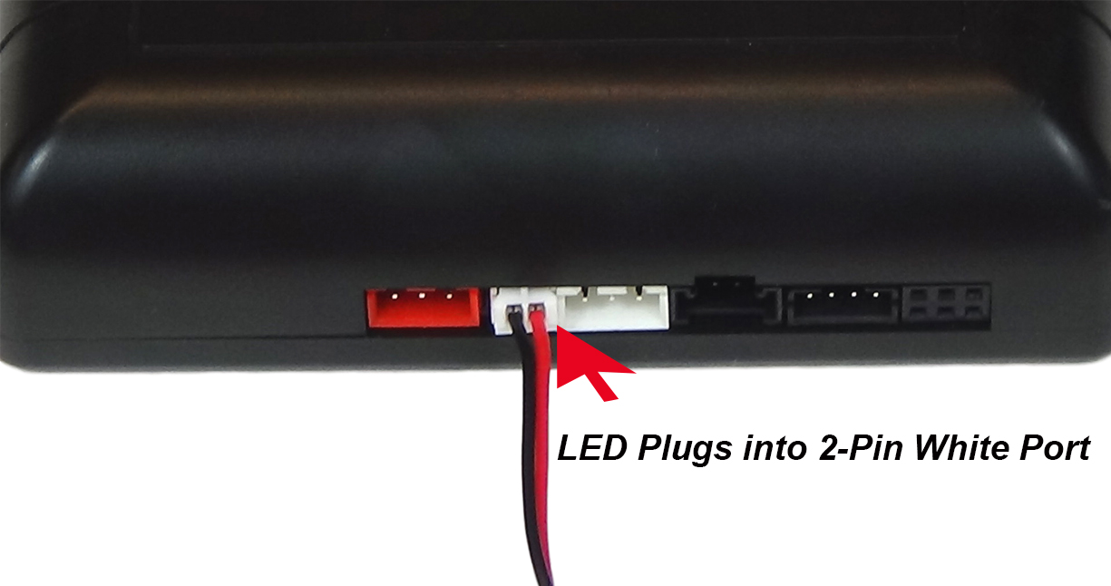
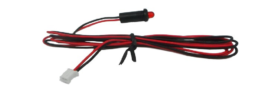
2. LED – The Crimestopper remote starter comes with an LED with a small white 2-pin plug. This is a status indicator and can be useful for diagnostics but is not essential for remote start operation. Requires a ¼” hole. Usually put in the driver’s kick panel (that’s the area forward of the door), the driver’s side of the center console, or the underside of the dash.
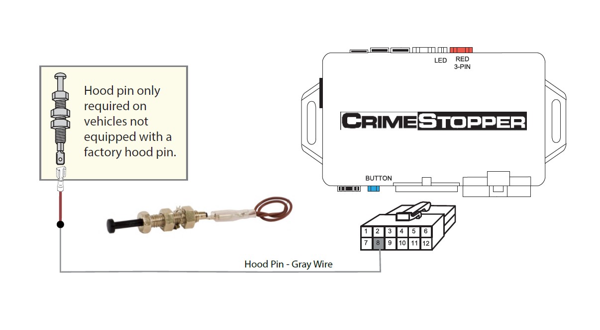
3. Hood Pin -This is an OPTIONAL connection and is not needed for the remote start to operate.
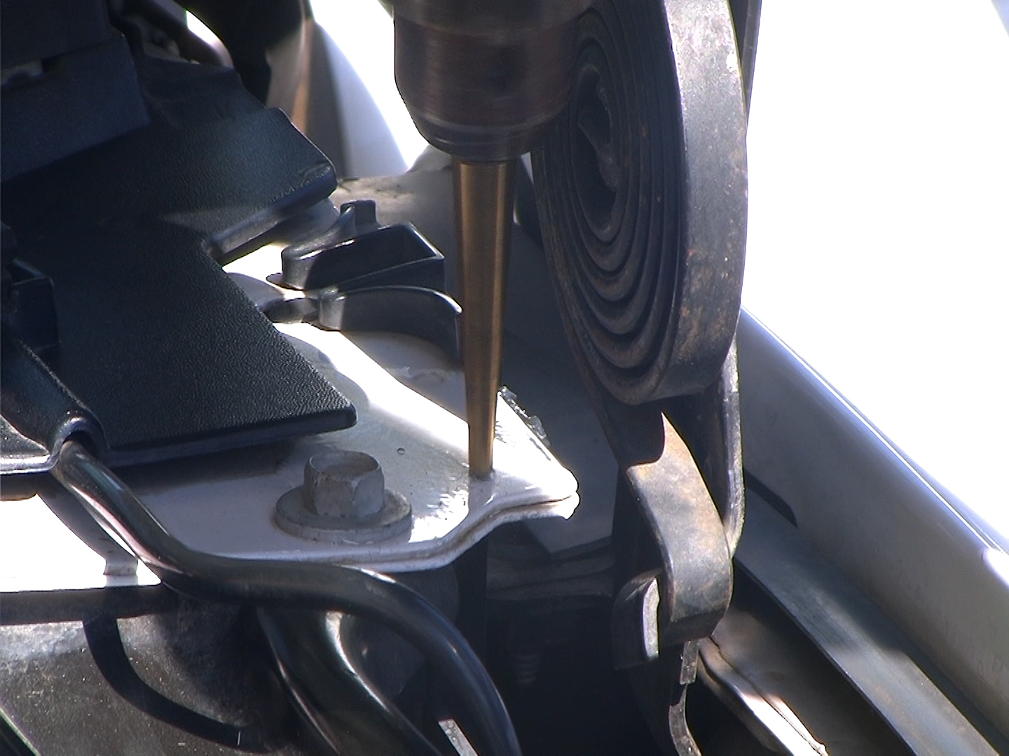
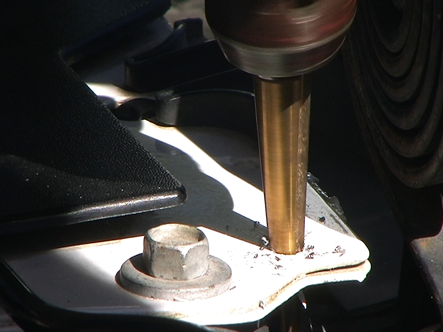
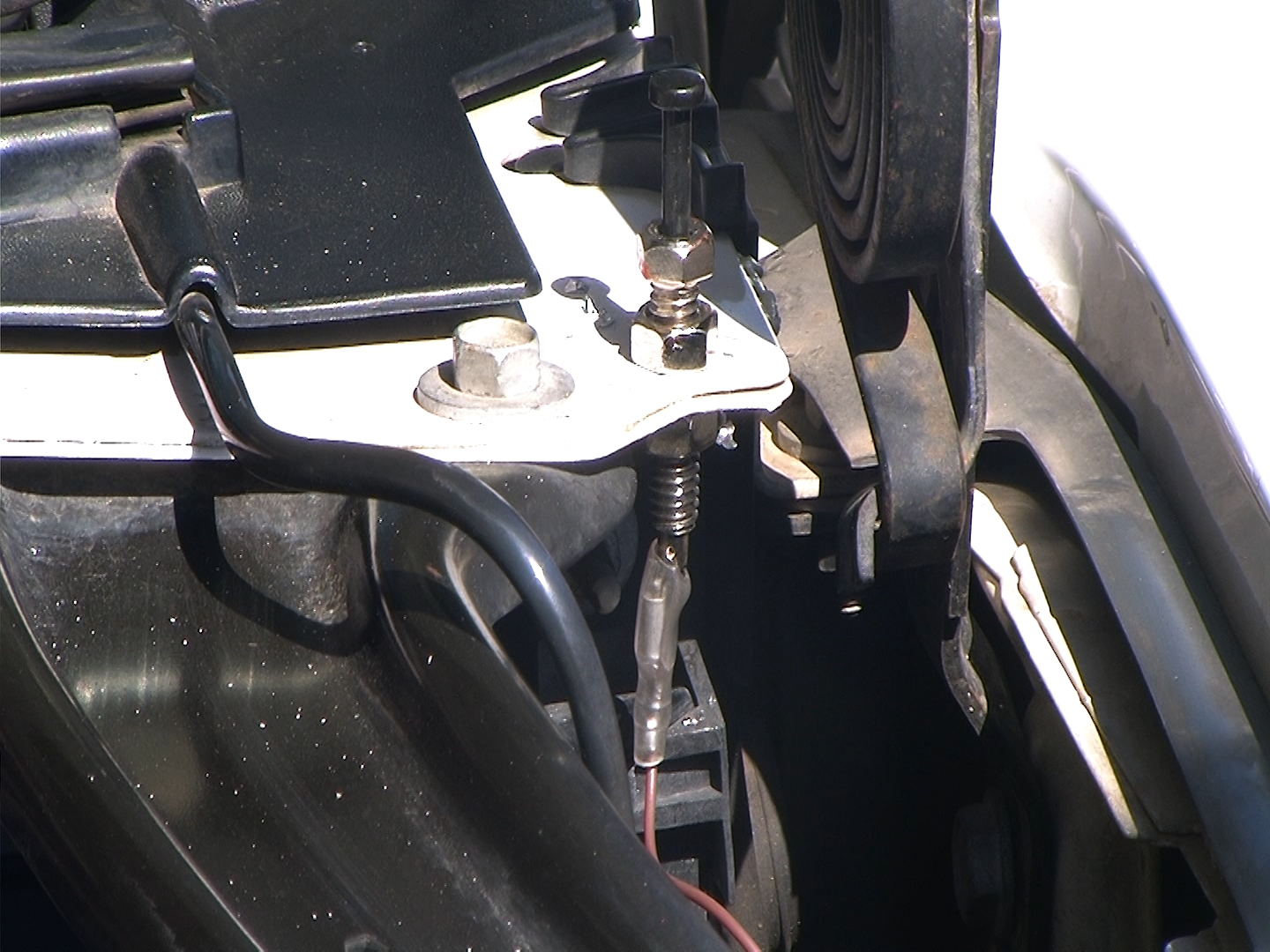
If your vehicle is not equipped with a hood pin switch you can install an aftermarket one as a protection feature. The hood pin will prevent you from accidentally activating the remote start if the hood is open. You will need to drill a 3/8” hole in metal under the hood and mount the aftermarket hood pin switch. Make sure that you position the switch so that when you close the hood it pushes the plunger down on the hood pin switch. Route a wire from the pin switch carefully through the firewall either by way of a plastic grommet or use a factory rubber grommet to pass the wire through. Then connect the hood pin switch wire to the Gray wire in the 12-pin connector as shown.
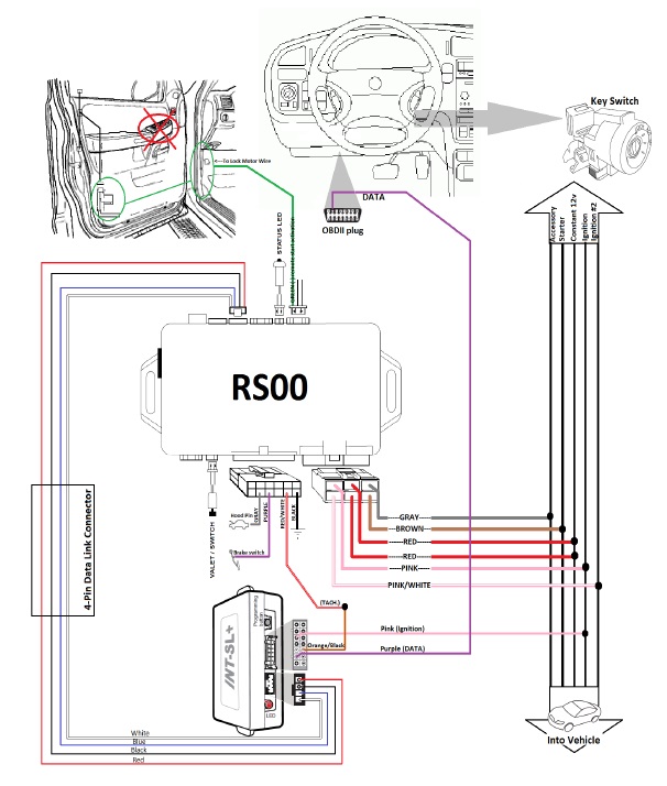
2004 Chevrolet AVALANCHE WIRE CHART: Crimestopper Remote Starter
| RS0 Wire: | Function: | Connect To: | ||
|---|---|---|---|---|
| Main | ||||
6-Pin Plug |
||||
| PINK | IGNITION 1 | PINK (+) @ IGNITION SWITCH HARNESS | ||
| GRAY | ACCESSORY | ORANGE (+) @ IGNITION SWITCH HARNESS | ||
| BOTH RED WIRES | CONSTANT 12V | RED OR RED/WHITE (+) @ IGNITION SWITCH HARNESS | ||
| PINK/WHITE | IGNITION 2 | WHITE (+) @ IGNITION SWITCH HARNESS | ||
| BROWN | STARTER | YELLOW (+) @ IGNITION SWITCH HARNESS | ||
| Secondary | ||||
12-Pin Plug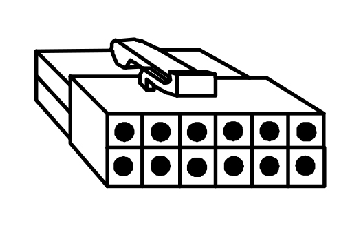 |
||||
| BLACK | GROUND | GROUND-SOLID METAL OF VEHICLE | ||
| GRAY | HOOD PIN | See "optional connections" section | ||
| WHITE | PARKING LIGHTS OUT | GRAY/BLACK (-) @ BCM UNDER DRIVER DASH, BROWN 24 PIN PLUG, PIN B2 | ||
| BROWN | TRUNK RELEASE | NOT USED - DO NOT CONNECT | ||
| ORANGE | OEM ARM | NOT USED - DO NOT CONNECT | ||
| RED/WHITE | TACH | CONNECT TO ORANGE/BLACK ON INTSL | ||
| PURPLE | BRAKE | NOT USED - DO NOT CONNECT | ||
| RED/BLACK | SELECTABLE PARKING LIGHTS ( + / - ) | GROUND-SOLID METAL OF VEHICLE | ||
| ORANGE/BLACK | OEM DISARM | NOT USED - DO NOT CONNECT | ||
| YELLOW | HORN HONK | NOT USED - DO NOT CONNECT | ||
| PINK | GLOW PLUG | NOT USED - DO NOT CONNECT | ||
| YELLOW/BLACK | GROUND WHILE RUNNING | NOT USED - DO NOT CONNECT | ||
| Low Current | ||||
RED 3-Pin Plug | ||||
| The green wire from the small red 3-pin plug of the remote starter takes a (-) signal from the door lock motor and uses that as a trigger to begin the remote start sequence. Here is the wire color and location, but you MUST use the included relay when making this connection. See the section below titled “Connecting the Start Activation Wire”. | ||||
| GREEN | START ACTIVATION | GRAY (+/-) @ DRIVER WINDOW SWITCH, BLACK 26 PIN PLUG, PIN 21 | ||
| BLUE/ORANGE | START | NOT USED - DO NOT CONNECT | ||
| ORANGE/WHITE | SELECTABLE IGNITION (IGN2/ACC2/START2) | NOT USED - DO NOT CONNECT | ||
| Door Lock | ||||
WHITE 3-Pin Plug | ||||
BYPASS WIRE CHART: INT-SL Interface Module
| INT-SL Wire: | Function: | Connect To: | |
|---|---|---|---|
| Main | |||
14-pin Plug |
|||
| LIGHT BLUE | LOCK | NOT USED - DO NOT CONNECT | |
| BLUE | GROUND WHILE RUNNING | NOT USED - DO NOT CONNECT | |
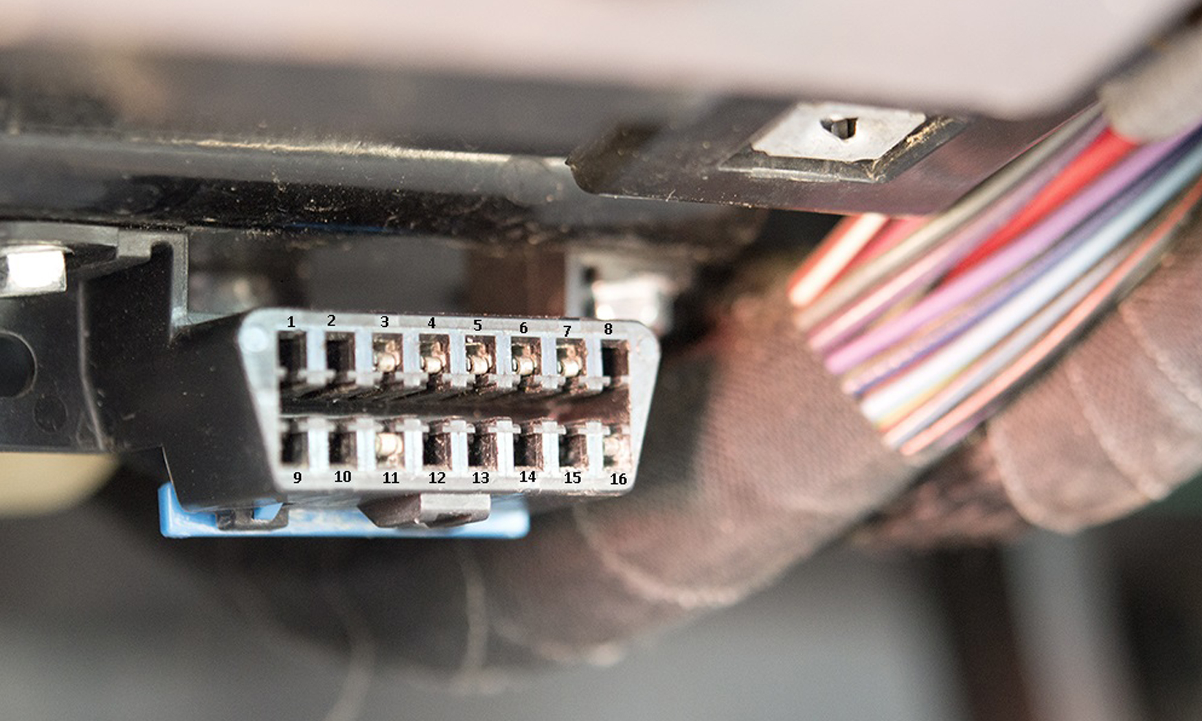
| PURPLE | DATA OBDII | VIOLET @ OBDII CONNECTOR UNDER DASH, BLACK 16-PIN PLUG, PIN 2 | |
| LIGHT BLUE/BLACK | TRUNK | NOT USED - DO NOT CONNECT | |
| PINK/BLACK | PARKING LIGHTS | NOT USED - DO NOT CONNECT | |
| ORANGE/BLACK | TACH BP | RED/WHITE @ CRIMESTOPPER WIRE IN 12-PIN PLUG | |
| YELLOW/BLACK | BYPASS PK3 | NOT USED - DO NOT CONNECT | |
| PINK | IGNITION | PINK @ CRIMESTOPPER IGNITION WIRE IN 6-PIN PLUG | |
| WHITE | UNLOCK | NOT USED - DO NOT CONNECT | |
| ORANGE | DOOR TRIGGER BP | NOT USED - DO NOT CONNECT | |
| YELLOW | BYPASS PK3 1 | NOT USED - DO NOT CONNECT | |
| WHITE/BLACK | UNLOCK DRIVER 2 | NOT USED - DO NOT CONNECT | |
| GREEN | FUTURE INPUT | NOT USED - DO NOT CONNECT | |
| PURPLE/WHITE | DATA BCM | NOT USED - DO NOT CONNECT | |
| Data-link | |||
4-Pin Plug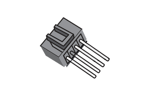 |
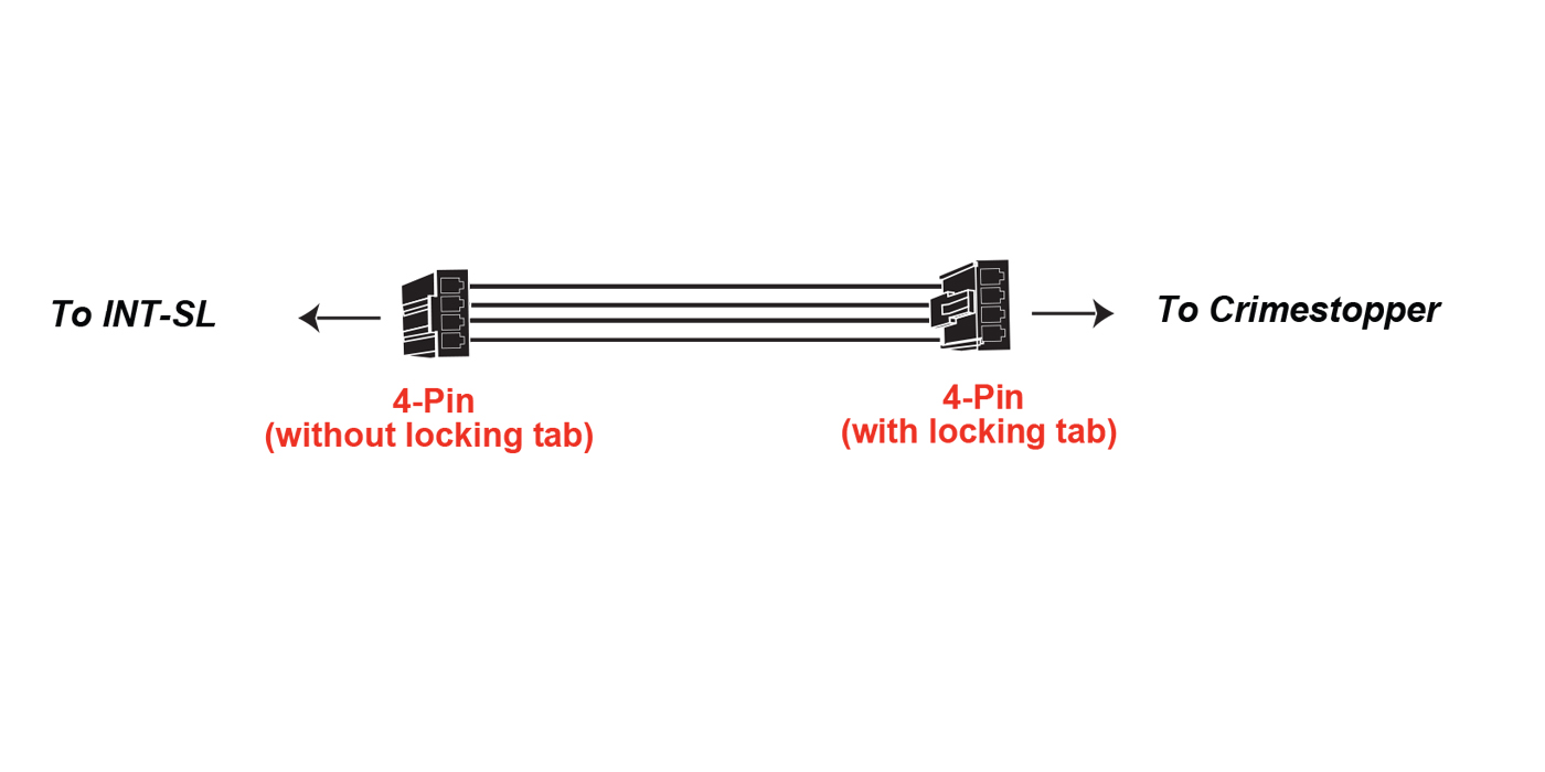 | ||
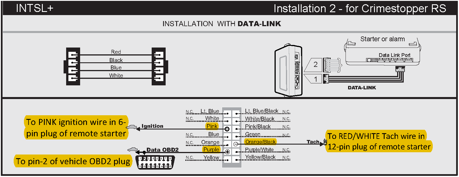
OBDII PLUG
The OBDII plug is a computer diagnostic port that a mechanic can plug a scan tool into and read your vehicles codes to troubleshoot potential issues. It is located under the driver's side dash in most cases. Some vehicles have it hidden behind a panel on the driver's side lower dash board. This is what the front looks like.
Connecting the Activation Wire
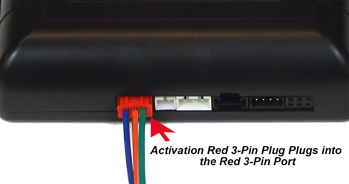
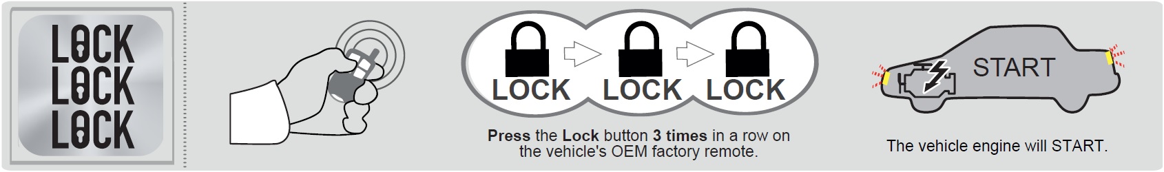
We have programmed option 17 in your Crimestopper remote starter to activate on three consecutive pulses. The green wire from the small red 3-pin plug of the remote starter takes a (-) negative ground pulse signal and uses that as a trigger to begin the remote start sequence. A relay needs to be added to convert the a (+) positive pulse of your vehicle door lock motor wire into the (-) negative that the remote starter needs to activate. That’s how pressing ‘lock’ on your OEM remote 3 times starts the vehicle.
The Crimestopper remote starter includes a regular red 3-pin plug with just loose wires at the end of it. You will not need to use that plug. We include an exclusive part in your kit to take its place. The LMM-CS is a micro relay that we have pre-wired for simplicity of install. Use this plug in place of the regular 3 pin plug in all applications. If your wire diagram requires you to install additional relays, such as second Starter or second Accessory relays then use the wires that come from the LMM-CS to make the connections to those additional relays as shown.
Use your wiring diagram to locate the “Start Activation” (Lock Motor) wire in the vehicle. Do not confuse the “Lock Motor” wire with the “Lock Switch” wire – they are different! Typically, the wire in the vehicle will be accessed at one of these locations:
• Drivers kick panel
• Inside the driver’s door
• Where the wires enter the vehicle from the door through the rubber boot.
Testing the correct wire will show (-) ground EXCEPT when the door locks are activated. At that time the wire will momentarily show (+) positive as the door lock motor is energizing, then return to (-) ground at rest.
Once you have identified the Start Activation (Lock Motor) wire in the vehicle, make the connections to the relay as shown on the diagram below.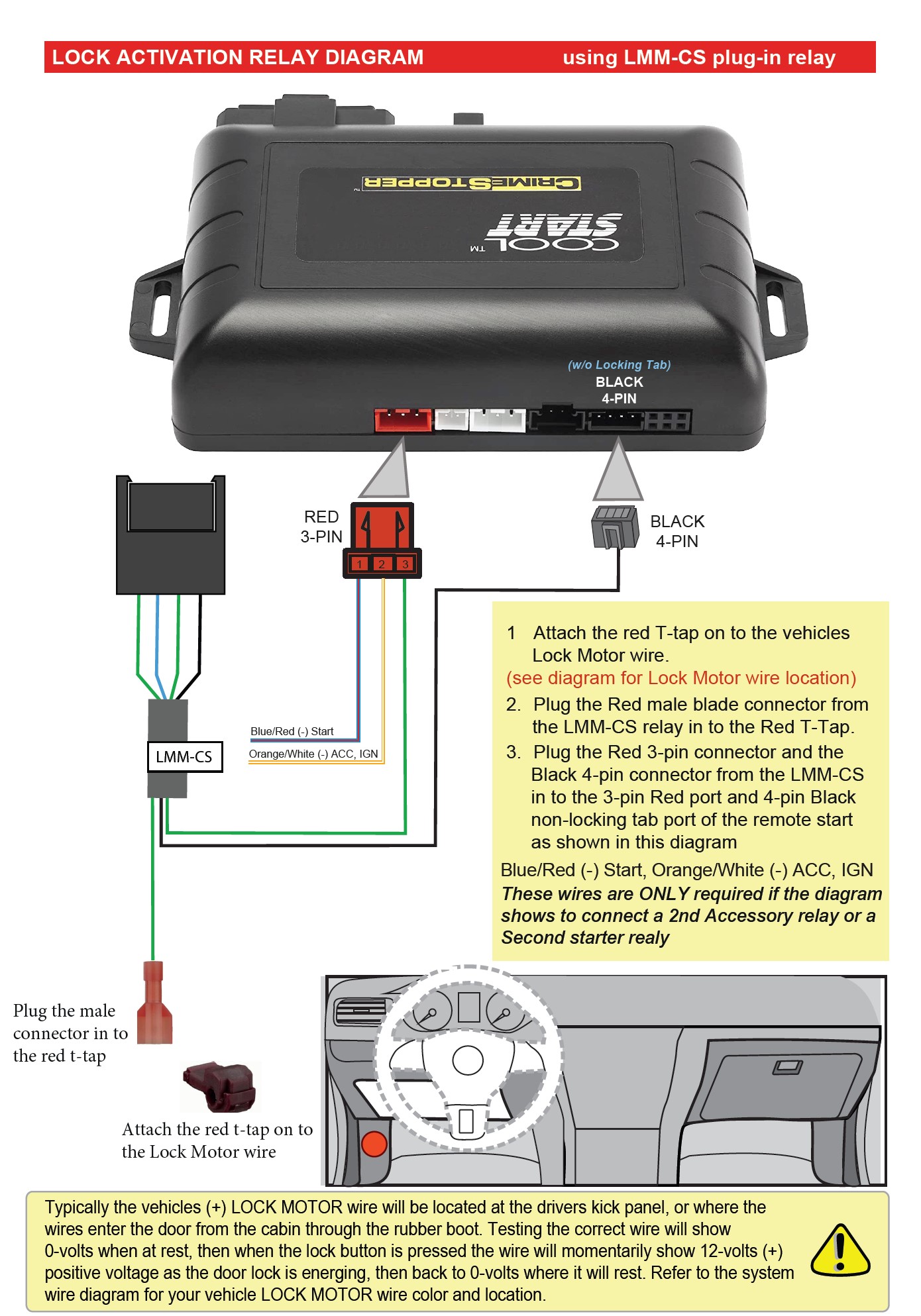
STEP 3: Programming
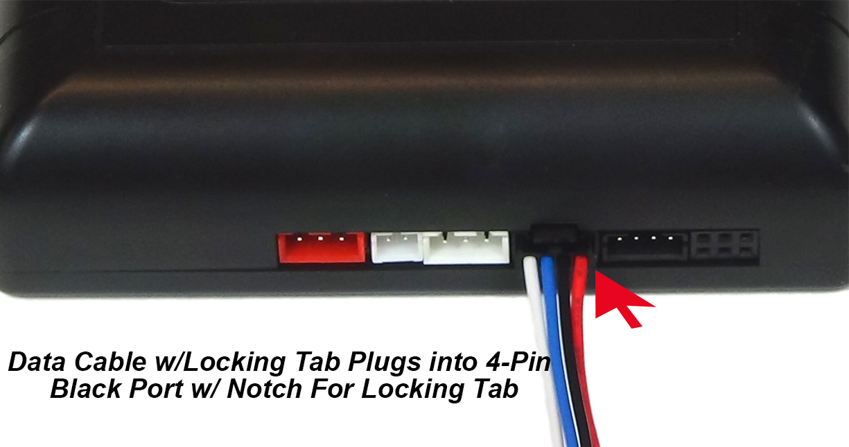
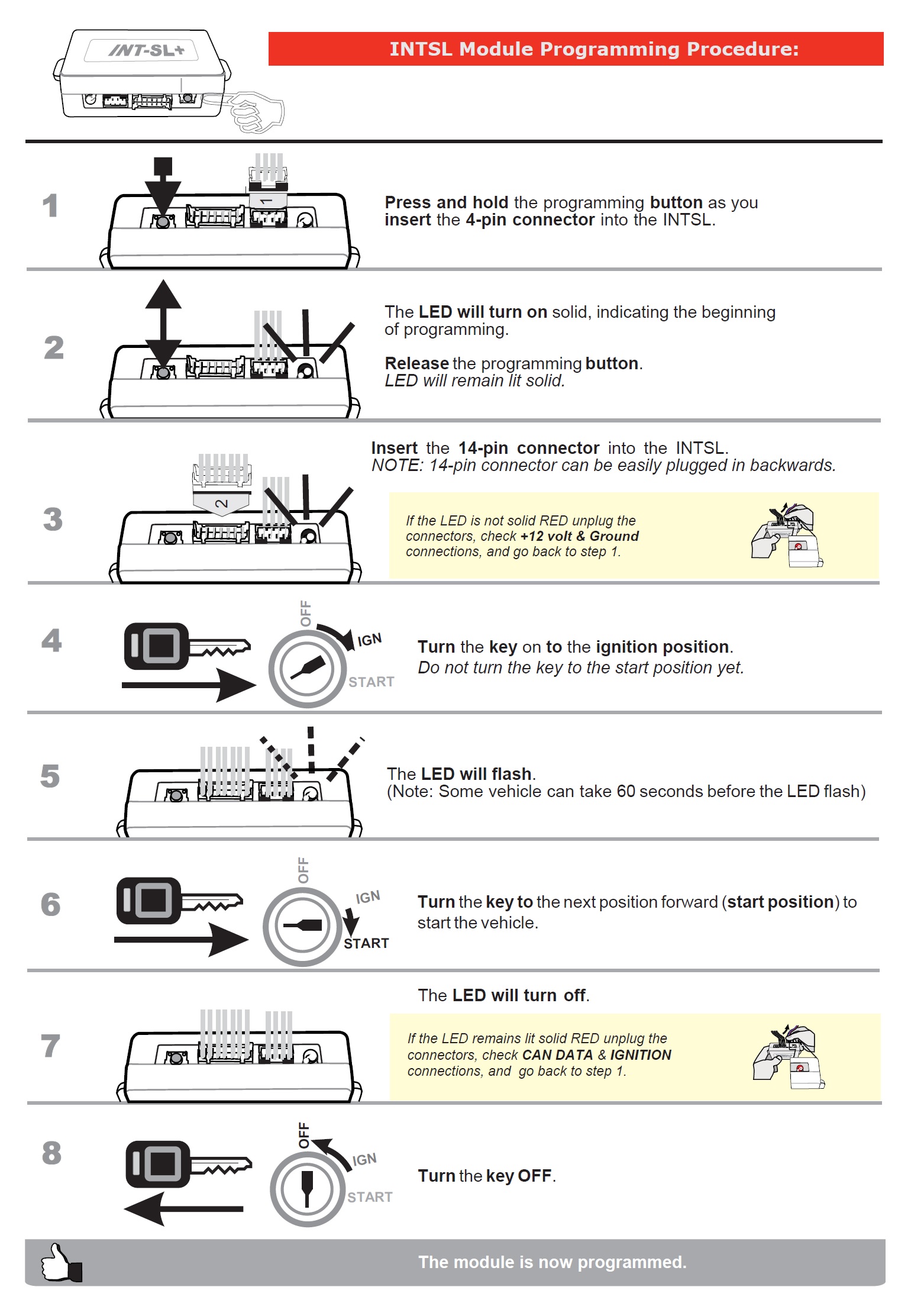
IMPORTANT - Before programming the INTSL, take note of the 14-pin connector. This connector is easy to plug in upside down. Make sure you have the two small ridges on the top of the 14-pin male plug aligned with the two small slots on the top of the female receptacle.
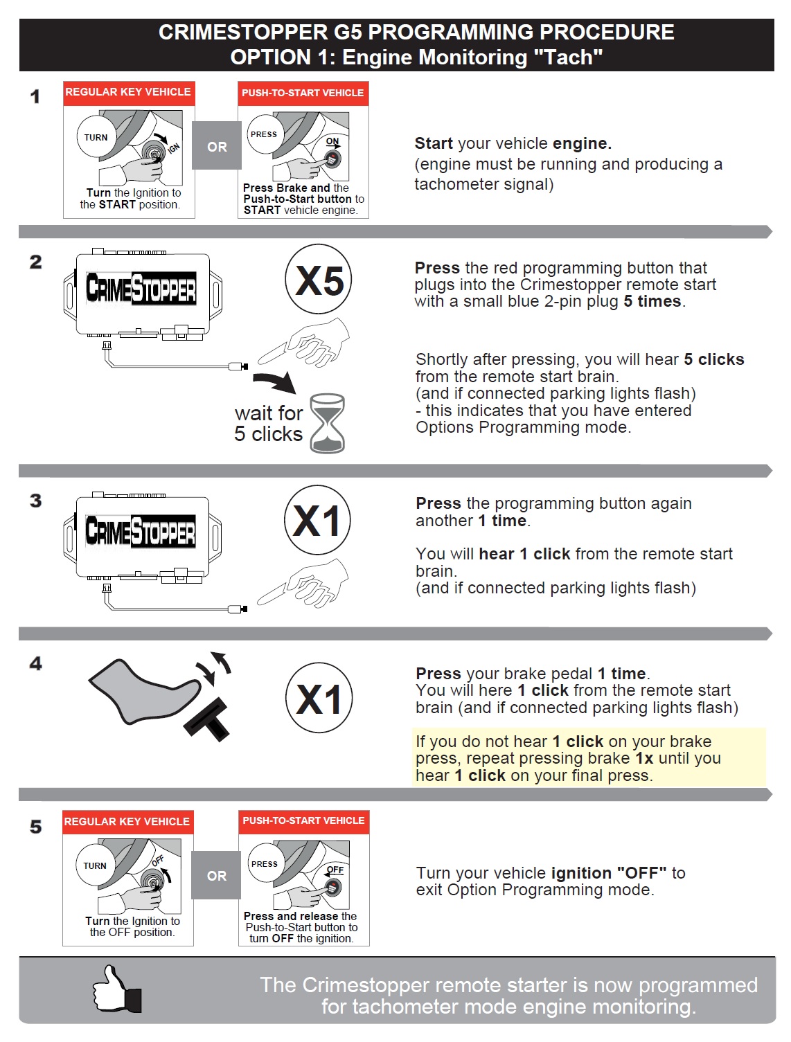
Tach Programming
Your remote starter has a built in engine detection circuit that tells it when the vehicle has successfully started and is idling. By default, the remote starter uses "smart tach" for engine detection. This will monitor the battery voltage increase when the vehicle starts and the alternator turns on. In most cases, this setting works reliably. If you do not experience any issue remote starting without changing this option, then there is no need to change it, so you can skip this step. Some vehicles will require tach programming. If the vehicle will remote start but will shut down after starting, or the plug in the LED flashes 5 times upon remote start failure indicating "Tach Error", then you may need to program the tachometer signal of your vehicle to the remote starter.
Kits that include a data interface module will automatically detect the tach signal of the vehicle through data with no extra wire connection needed. Kits that do not include a data interface module will require that you connect the red/white wire from the 12-pin plug of the Crimestopper remote starter directly to the vehicle tach wire.
The programming process is easy. First, make sure you have the valet/programming button plugged into the Blue 2-pin port of the remote start. Then, follow the steps below:
OPTION 19 - Diesel Glow Plug Delay
This option controls the delay between the time the remote starter powers the ignition and the starter. This is only needed for some diesel engine applications. If you have a gas engine or your diesel engine does not require a wait to start time, then you can skip this step.
To change this option follow the directions below:
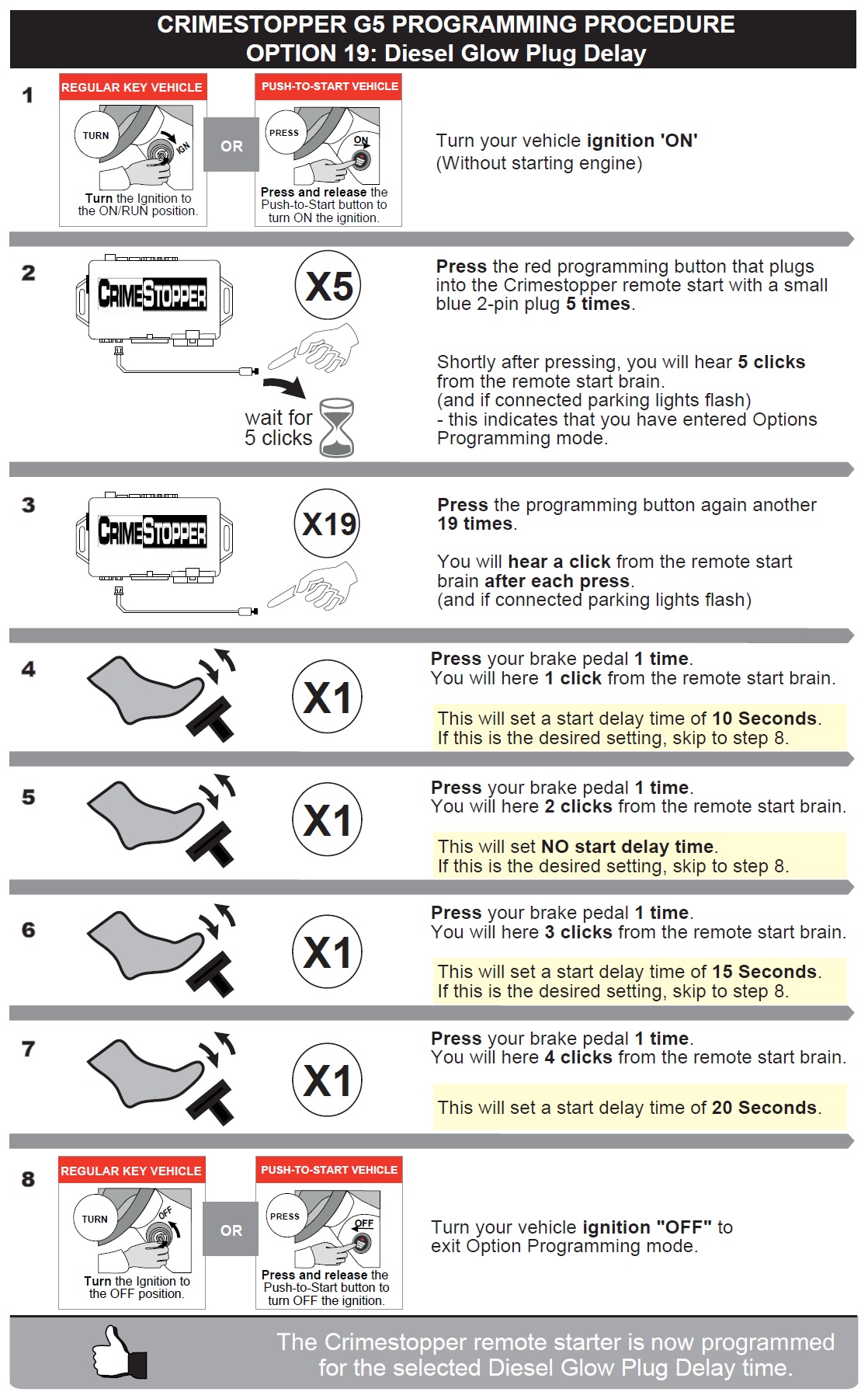
➢ Use the procedure below to make any programming option changes using your vehicles key, the vehicle’s brake pedal, and the valet programming button that plugs into the Remote Starter.
1. Turn Ignition Key to the ON position. Do not start vehicle (only start vehicle if programming option 1)
2. Press the Program / Valet button 5 times. A few seconds later you will hear the Brain click 5 times.
3. Push the valet program button the number of times that corresponds to the option number desired. You will hear the brain click with each button press. If the system did not flash the lights and/or honk and/or click, then it did not register your press. Press carefully and do not lose count.
4. When you reach the desired option #, to change the option: Press the brake pedal the number of times that corresponds to the value of the option to be changed (the same # of RS clicks as brake pedal presses will be heard).
5. When finished, turn Ignition OFF, and check for changed features.
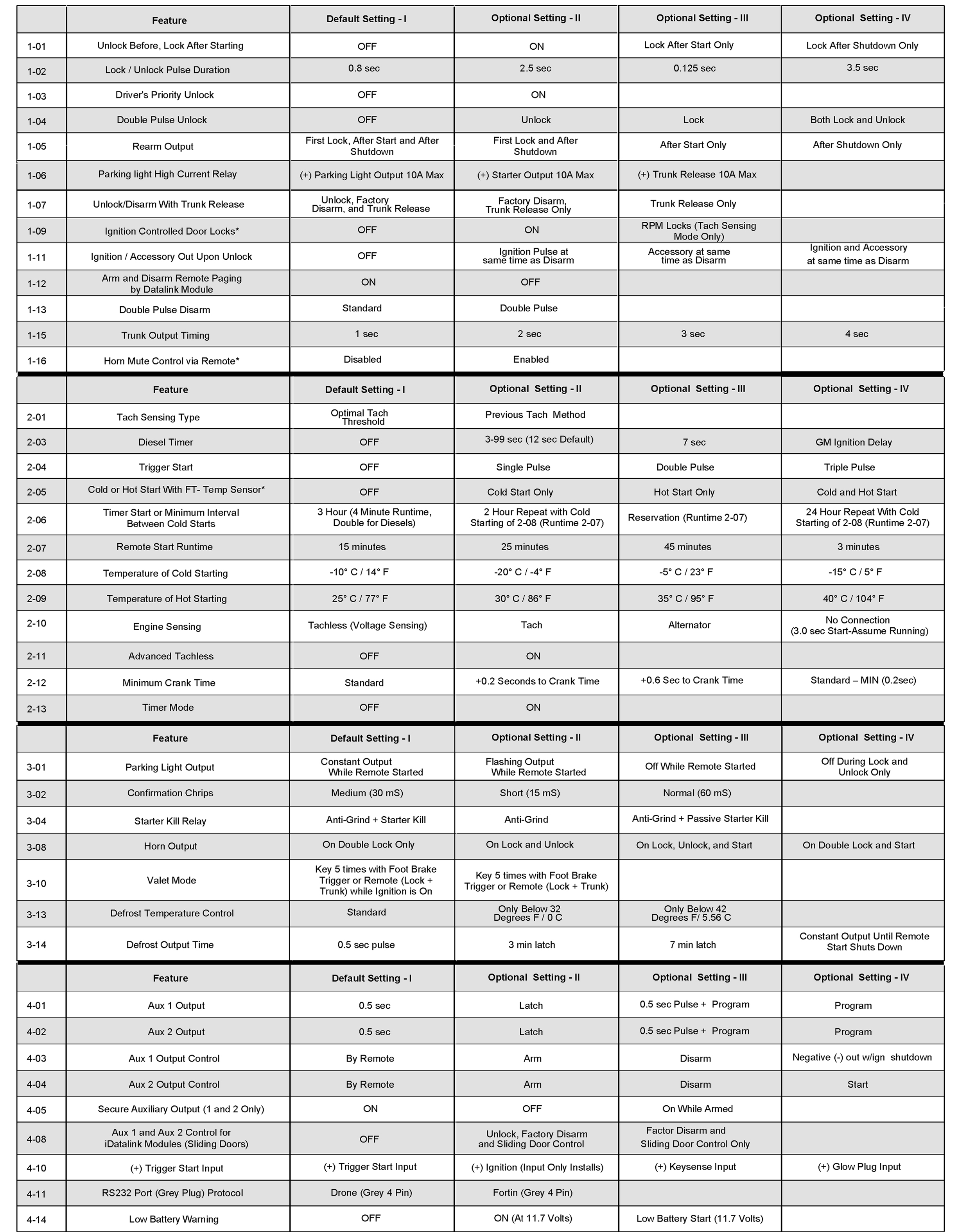
If you wish to change any options to customize the functionality of the remote starter, a matrix of all programmable features and their options are on the following page:
STEP 4: Testing the system
Once all wiring and programming are done, you should test the system to make sure everything is working properly before you close up the installation.
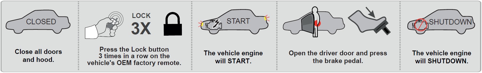
1. With the key removed from the ignition, press the lock button on the vehicle factory remote three times in succession. Timing is important! Pressing the lock button too fast or too slow will not activate the system. The presses should be about 1 second apart.
If everything has been installed and programmed correctly, a few seconds later the gauges will power up and the parking lights (if connected) will flash, and a few more seconds later the vehicle will start.
2. Make sure the vehicle stays running, and that the climate controls are working.
The engine will remain running for the programmed run time or until the brake pedal is pressed. If your factory remote stays operational while the vehicle is running (on some vehicles it does not), the engine can be turned off by pressing lock 3 more times on your factory remote.
3. If your test was unsuccessful, go back and re-check your wiring and programming. If you used T- Taps, make sure they are all attached correctly. Poorly made T-Tap connections are the #1 cause for tech support calls. Also, remember that T-Taps should never be used on data connections. Depending on the vehicle, those connections could be labeled Data, Can Hi, Can Low, IMMO, IMI, RX, TX or Passlock.
STEP 5: Finishing up!
After confirming that everything works properly, cap off or tape the ends of any wires you’re not using to avoid grounding or other contacts.
• Now gather up all the wiring and neatly bundle it together using zip ties or electrical tape to prevent the wires from interfering with any of the moving parts under the dash.
• Test the system often when you are putting your vehicle back together.
• Find a secure place to put the remote start module and use zip ties to secure it. Be careful not to zip tie near your connections as it may create a bad connection.
• Replace any interior vehicle panels that were removed to gain access to the needed wires, in reverse order that they were removed.
• Test the system as you reinstall the panels in your vehicle to make sure you do not pull something loose or pinch a wire. Be careful not to run a screw through a wire or pinch a wire while reinstalling panels.
KEY TAKEOVER
Copyright 2026 Digitel LLC